(This is a text transcript companion article to the video above.)
Disclaimer
Calibrating a Vectrex requires adjusting live components while 6,000 volts run from the high voltage wire to the picture tube. This can be lethally dangerous especially for those unfamiliar with the internals of CRTs. Proceed at your own risk.
Introduction
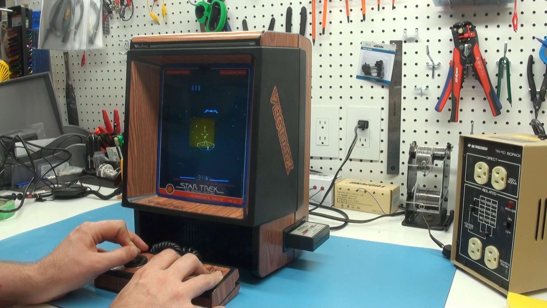
Are you feeling off-kilter? Drifting aimlessly through time and space? Seeing lines in every direction or words that just don't make sense? Is something askew? Well, I can't fix you, but with a little TLC we can restore any mess of a Vectrex with similar symptoms back to pristine condition.
Here's my definitive guide on running the full gauntlet of checks and adjustments to return your Vectrex to perfection. Timestamps for each task are included in the description, but I recommend watching it in full at least once before diving in so you understand how each control affects the system. Given the fragile nature of vintage components, the principle of "if it isn't broke, don't fix it" strongly applies.
Normal Imperfect Behavior: This Is Fine!
Before we dive in, note that there are several normal imperfections across all Vectrex systems that are part of common operating behavior. Remember, this was a mass-produced consumer product where affordability was key, not a precision grade piece of tech.
- As soon as you turn the power switch on, an audible buzz regardless of volume is expected except in user-modded sets or late-model production runs.
- If a game play fine but you see a white dot in the center, reduce the brightness on the back.
- A perfectly working set will still show subtle degrees of jitter or wobble depending on the game, especially noticeable at the extreme edges and on tiny vectors.
- Certain sequences involving a sudden increase or decrease in on-screen graphics or intensity can result in momentary variance in width or height.
- Flickering is natural and becomes more pronounced as the number of on-screen vectors increases, which is why some games are affected more than others.
- Screen overlays can help mitigate these small visual distractions, but it all becomes second nature after a short time playing.
Prerequisites
These checks are comprehensive in nature and often overkill for correcting specific problems. That said, here are the various groupings of test equipment you'll require depending on what tests you wish to perform.
- For foundational checks and adjustments, you'll need a Philips screwdriver to open up the case, a multimeter, and an adjustment tool for making internal calibrations — an insulated flat-head screwdriver will work in a pinch.
- To check the CRT's high voltage, you'll need a specialized high voltage probe (e.g., BK-PR-28A). This connects to a standard multimeter and allows reading up to 40,000 volts.
- Advanced calibration will require an oscilloscope, be it an old analog style or a modern digital.
- An isolation transformer is strongly advised if you'll be performing any of the oscilloscope tests. I've set mine to 120 volts to match US-based AC voltage.
- ESR meters (e.g., MESR-100) can be useful to quickly check in-place electrolytic capacitors to find any with wildly out of spec measurements.
- For the most accurate calibration, you should get a copy of Test Cart Version 4. This program is also included on multicarts. There's an accompanying overlay for it that can be convenient especially for centering but is not mandatory.
- Finally, a mirror can be handy while making adjustments so you don't have to hunch over the front.
Disassembly and Inspection
We only need minimal disassembly for all of the adjustments in this video. If you are doing a full recap there are a few capacitors that'll require further disassembly of the logic and power boards.
The Vectrex can be opened up by unscrewing the four corner screws and one longer screw in the bottom center.
Then, with the Vectrex upright you can gently pull both halves apart at the center seam. It's a little easier if you slightly tilt the machine forward while pulling from the back.
The back half of the case is only a plastic shell and can be set aside. Be very careful with the front to not bump or otherwise damage the neck of the tube.
If this is the first time you opened the case, you might find a lot of dust that can be roughly cleaned up with a brush and some compressed air.
Now's a good time to inspect the capacitors to make sure none are leaking or peculiar. The large filter caps have glue applied to their bases from the factory, so don't be alarmed if you see that. In my case I found one improper looking cap and an unusually loose polystyrene cap. Good candidates for replacing but since I know the Vectrex is already functional enough to see a display, I'll do all the other adjustments first to see if the machine still needs additional help.
Fuse Test and Replacement
If your Vectrex is dead without a trace of life when you try powering it up, the fuse is a good candidate to check. There can also be times where the fuse is operational yet defective enough that it causes intermittent voltage fluctuation that can lead to a variety of on-screen defects.
The fuse is accessed under the orange cardboard cover on the logic board, with one screw holding the cover on and another holding the fuse PCB down.
Set your multimeter to continuity mode, preferably with beep enabled, and place each probe on opposite ends of the fuse. Dead fuses won't have any continuity so you won't hear a beep or see any value, meaning it needs replacing.
If the fuse works but close inspection shows granular artifacts or during operation you see drastic and continual change in width and height, it's worth replacing.
In the US the set uses hardwired 0.5 amp, 125V or higher slow blow fuses. You can replace them with more common 0.5 amp fuses if you install an internal or external fuse holder, or you can find ones with leads on for direct soldering from Console5.com.
Basic Voltage Checks
Voltage checks can verify stability or pinpoint severe misfunction. Power on the Vectrex to begin.
Start with the transformer outputs. Set your meter to AC and place the ground probe at the common point, then touch the red probe to a point on either side. A rating of 8.5V to 11VAC is expected. Swap the red probe to the other side; the voltage should match. If one side has no output, it might be a defective power switch.
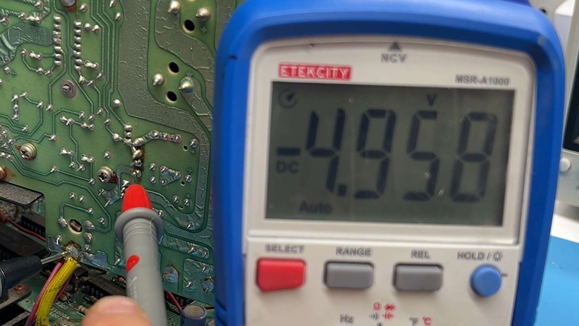
Next, the power rails leading to J204. Switch to DC mode and connect the ground probe to any ground on the Vectrex. Touch the red probe to the bottom pin here, which should read -5VDC. Next up is 0V ground, then 5VDC, then -13VDC.
Finally, check PIN 3 of IC301 on the logic board, which should read -13VDC. There are other places to check voltages, but if these ones line up then you're usually in a reasonable state to proceed. A total lack of one voltage line could be a bad voltage regulator or power transistor.
DAC Offset Adjust (Oscilloscope or Multimeter)
A mis-calibrated digital-analog-converter can result in the entire screen being offset or squished toward one corner. In extreme cases the screen will cut-out entirely. We want to adjust the DAC offset to 0 volts using either an oscilloscope or multimeter.
Using Test Cart Version 4, press button 4 to get to DAC Offset mode. This will cycle between text and a black screen every few seconds.
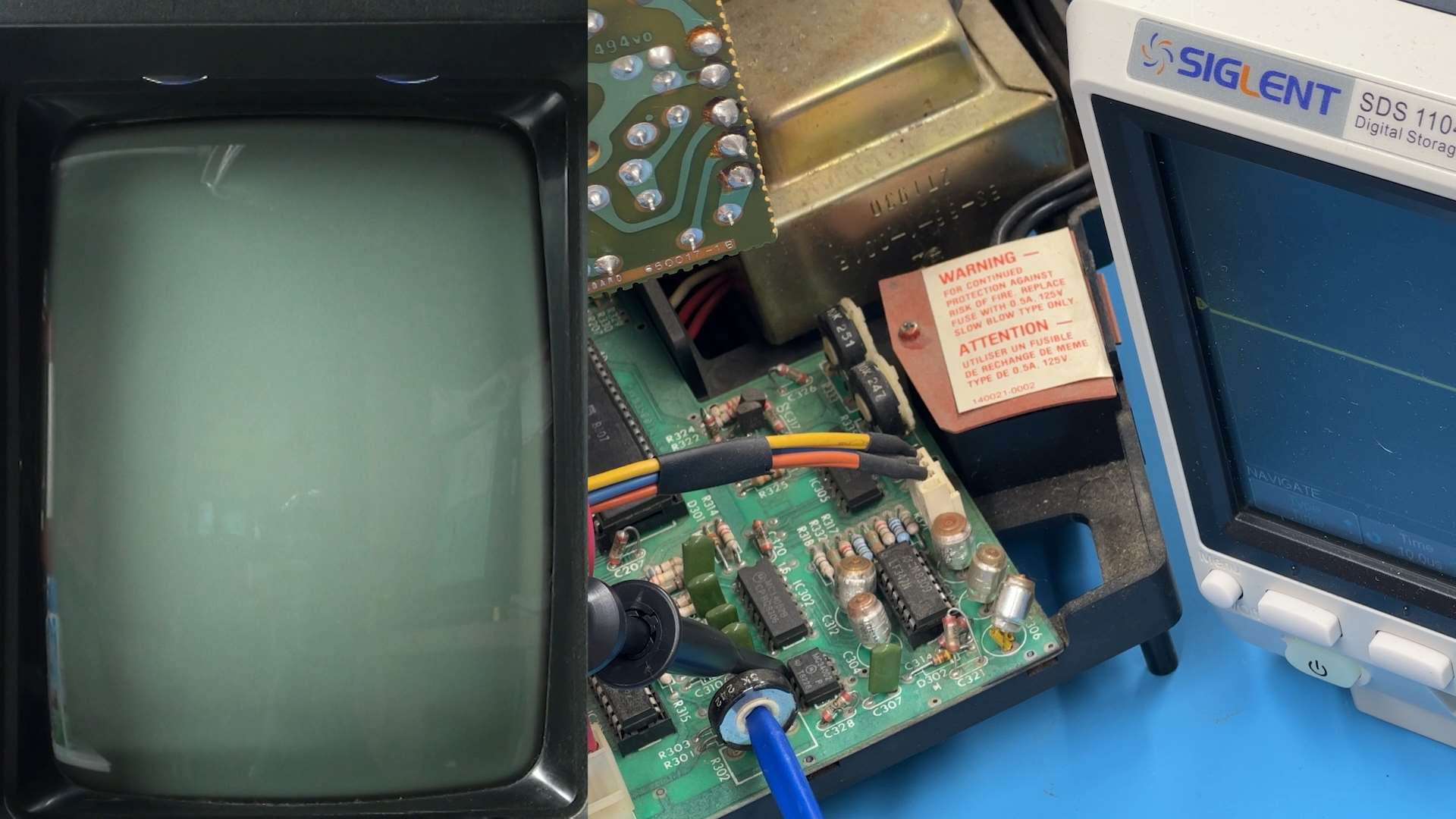
On an oscilloscope, start at 100 millivolts/div and 10uS. Connect the ground and attach the other probe to PIN 1 of IC304. When the screen goes black, a solid line will appear. Adjust R302 to center this line at 0 volts. Then lower the volts-per-division down to 5 millivolts and subtly fine-tune it to perfection.
With a multimeter, connect to the same location and review the DC voltage when the screen is blank to tune it down to 0. The adjustment is very sensitive so turn very slowly.
High Voltage Calibration
To check the CRT's voltage you'll need a high voltage probe, and this is where we deal directly with dangerous energy so be careful. Plug the probe into your DC-set meter. Turn the brightness knob all the way counterclockwise to kill the brightness.
Connect the ground of the high voltage probe to your Vectrex. Then touch the high voltage probe to the HV lead in the CRT. Multiply the reading by 1,000 to get the true voltage.
This set reads nearly 7,600 volts, which is way above spec.
Hook an oscilloscope to pin 7 of the flyback at 10 volts per division and then carefully adjust R526 until the ringing on these valleys and peaks smooth out. Now reconnect the HV probe to check the voltage again. While monitoring the voltage, adjust R525 so it settles around 5,800. Anywhere from 5650 to 5950 is within spec, and being in the 6000s is acceptable.
IC501 Timing Adjust
As an alternative to manually altering the high voltage, R525 and R526 can be used to fine-tune the flyback timer at IC501 instead. This approach doesn't require a high voltage probe, only an oscilloscope.
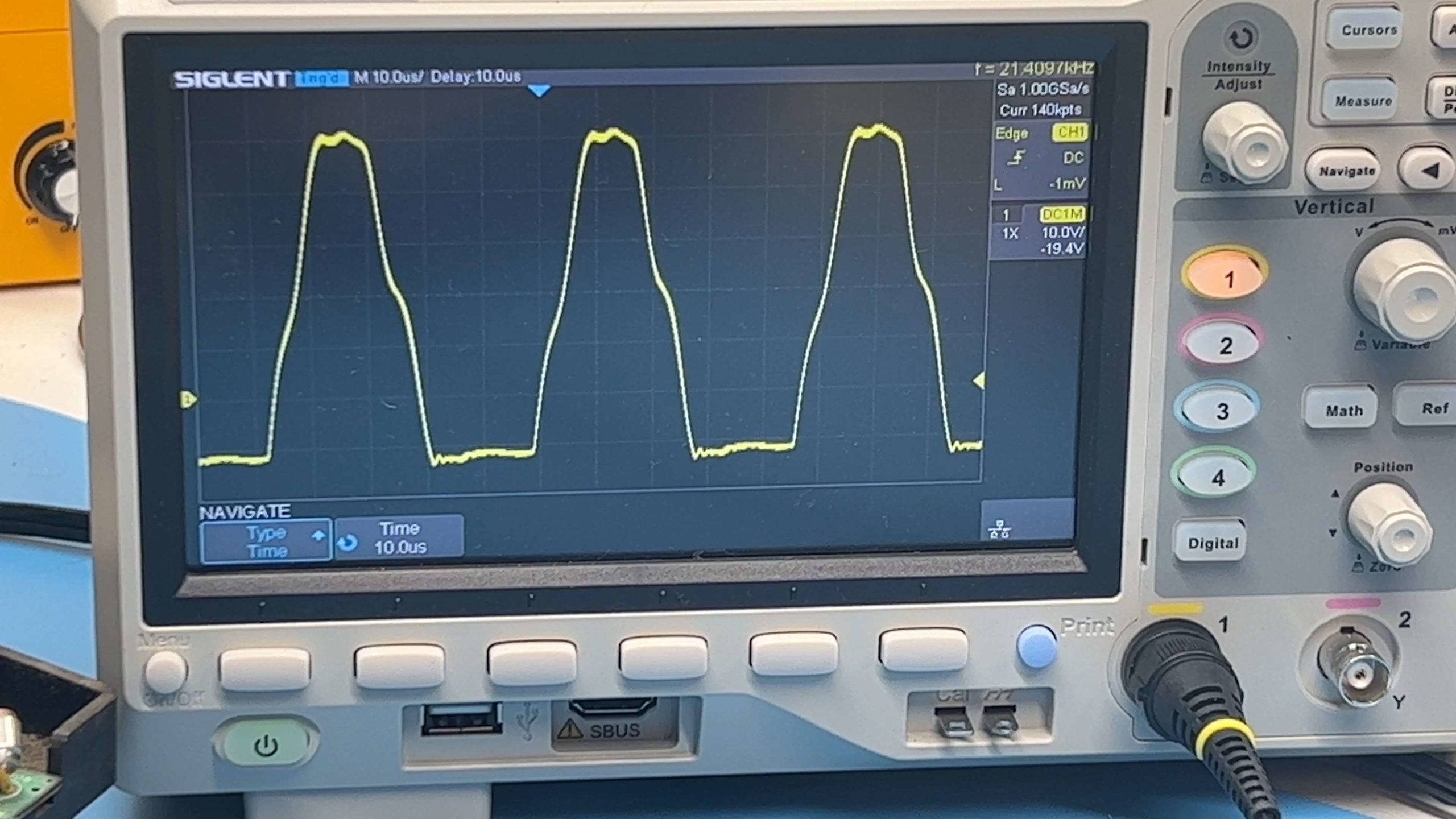
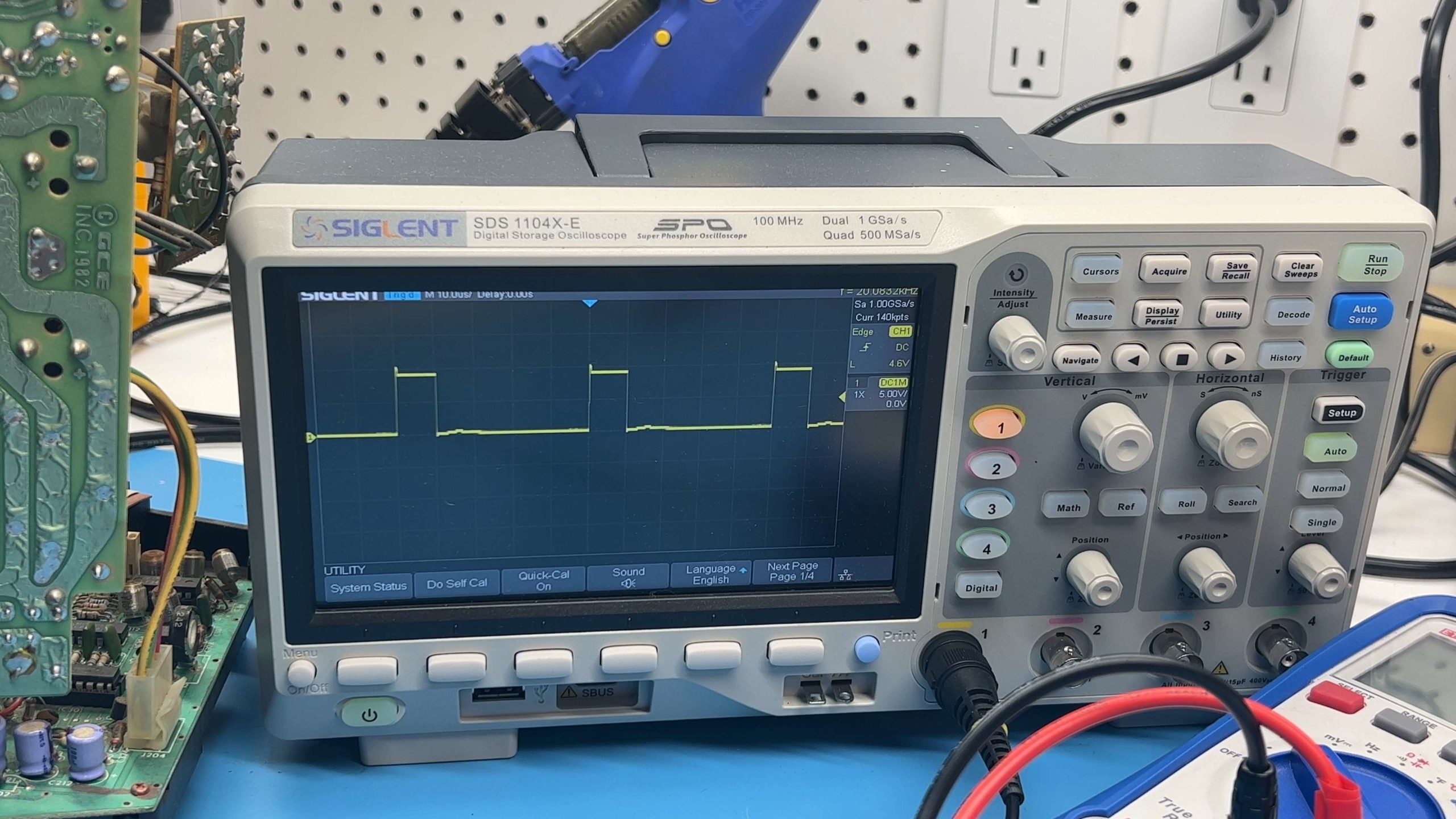
In the back of the official Vectrex troubleshooting manual, the desirable wave form of IC 501 is illustrated. For every 10 microseconds of voltage, 40 microseconds of nothingness should follow. Getting these values aligned will ensure maximum stability along the flyback track.
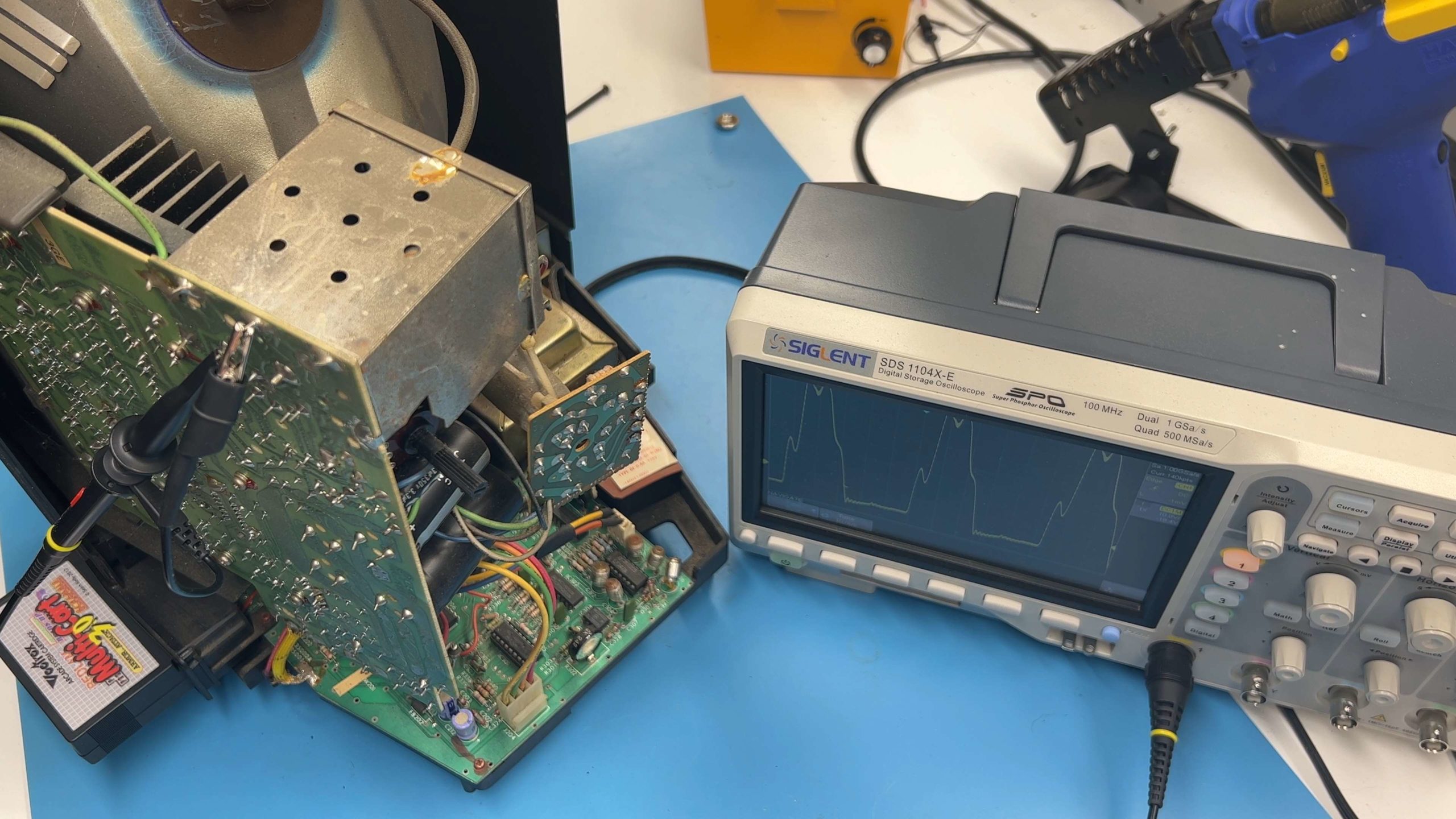
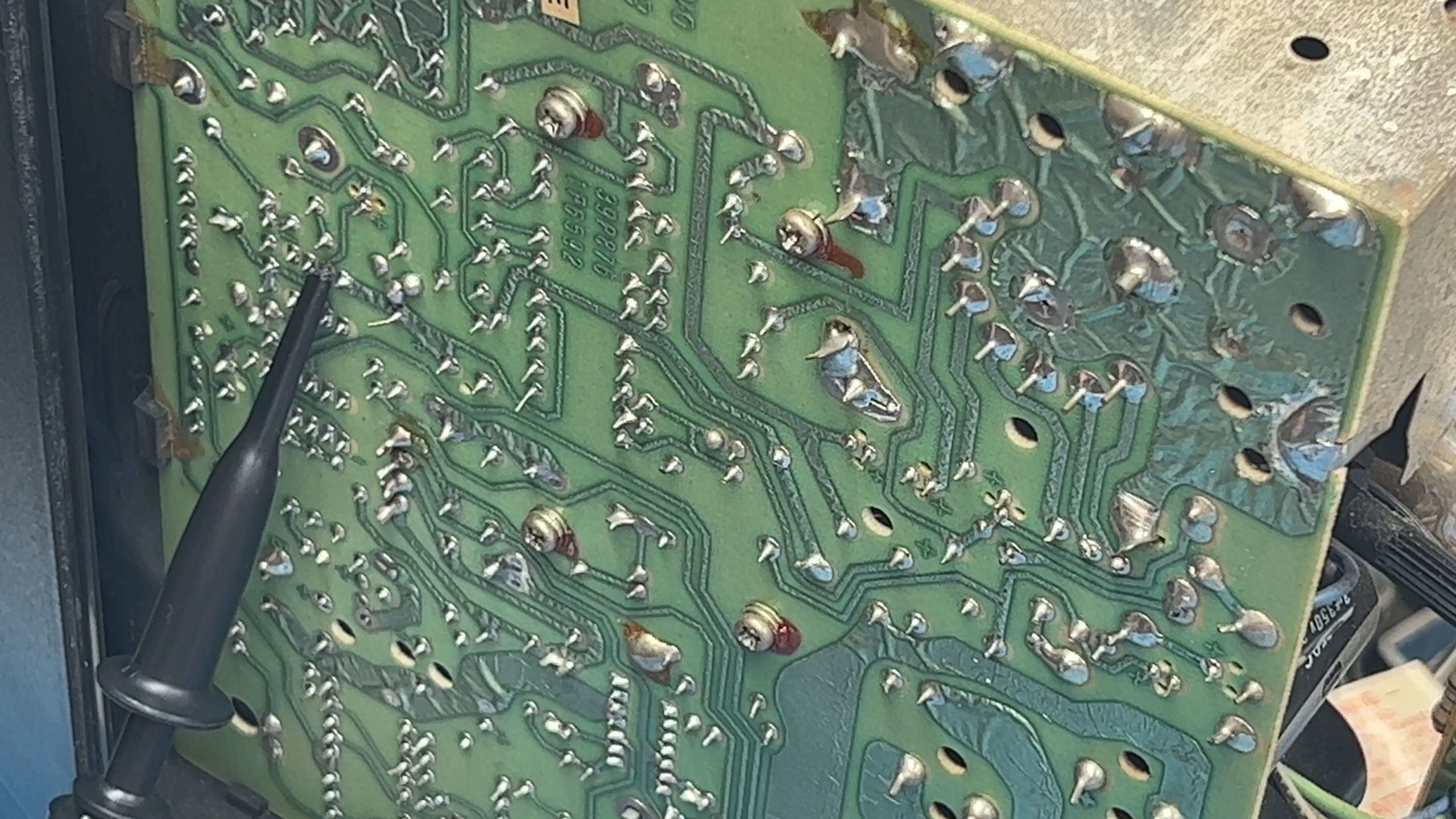
To observe the waveform we have to connect our scope to PIN 3 of IC 501. We can do this from the back of the power board if we are careful to find the right pin, as illustrated.
You can see in this example the peaks are slightly too wide and the valleys too thin. Adjust R526 to adjust the 0 volt gaps to last 40 microseconds, and then adjust R525 so the peaks are 10 microseconds long. This will generally increase your overall HV voltage slightly once calibrated.
Screen Width and Screen Height
The Vectrex has various adjustments for fine screen control to remedy stretching, skewing and offset graphics. Let's begin with the width and height controls. Make sure the brightness is back to a viewable screen state before beginning. We'll fine-tune the brightness in a bit.
If you have Test Cart Version 4, start it up so that the main grid is shown. Each box of this grid should be relatively the same width and height. There are two adjustment controls on the power board to manage overall screen dimensions.
Although you can access these controls from the front of the power board, there are two small cut-outs in the back to make it much easier. Using a small adjustment tool or flat screwdriver, you can turn the controls one direction or another to alter the width and height.
R401 adjusts the horizontal width of the screen, while R408 controls the vertical height. The idea is to adjust both so that the tiles are relatively square and the long lines on all four sides are fully viewable on the screen.
Screen Centering
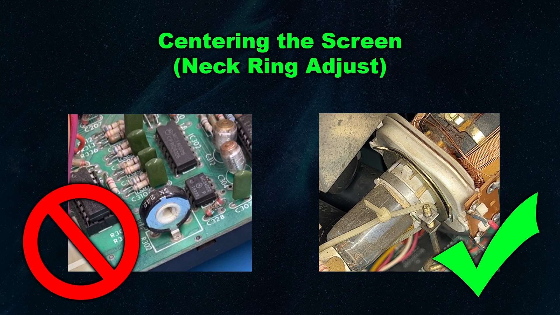
I've seen bad information in other guides advising to use internal pots to center the Vectrex. The service manual specifically warns against using any pots for centering. The centering process is much more traditional, relying on the two adjustment magnets on the back of the yoke around the tube.
This is another task that requires interacting with the tube itself, which again has a lot of high voltage feeding through it while you work. The metal rings on the neck are safe to touch with your hands while the set is running, but there are a lot of high voltage components surrounding them so use extreme caution.
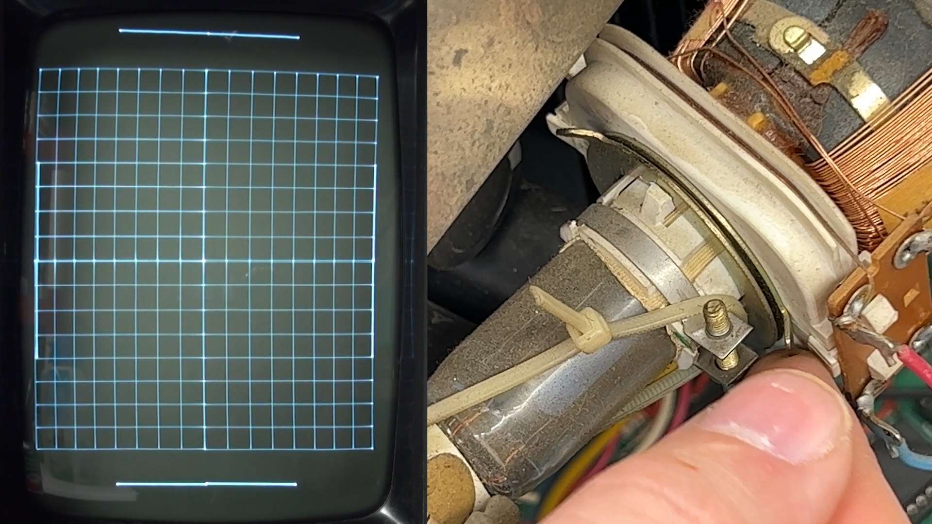
You will see two rings with tabs that can rotate independently from one another. There may be glue or adhesive holding them down. It's not a bad idea to mark the location of each before you start so you can revert back if needed.
Rotating the ring closest to the front of the Vectrex will control the horizontal position, and the one closest to the back controls the vertical. Adjust both of them until there is equal space on all sides.
If you have the overlay, you can insert that to more precisely find the center point. After completing this step, you may want to re-adjust the width and height as described.
Integrator Offset
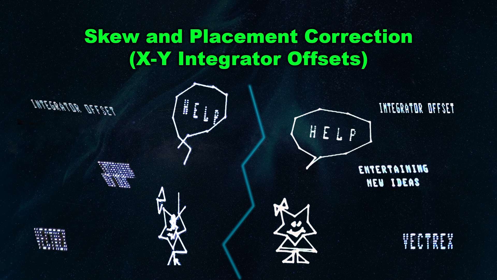
One of the most common symptoms of aging Vectrex machines is the appearance of skewed text or disconnected lines in graphics. This most commonly relates to the X and Y integrator rates, which can be adjusted internally.
You can perform these adjustments with any screen that displays detailed graphics and text, but the test cartridge has a specific integrator test for this cause. Switching to this test will display a matrix of diamonds.
On the logic board, R333 controls the vertical or Y rate, and R335 controls the horizontal or X rate. Using the test screen, rotate each control individually until the lines forming the diamonds perfectly merge with no overlap or displacement. Pay special attention to the bottom row of diamonds and use those while making this calibration, as that is the most crucial row to get right.
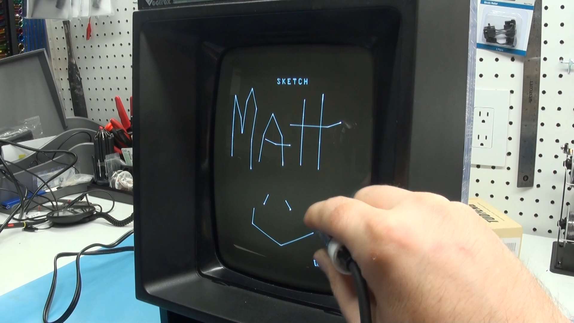
Once this is done, you should notice text and imagery is much more aligned and readable than it ever was before.
Brightness (Intensity) Optimization
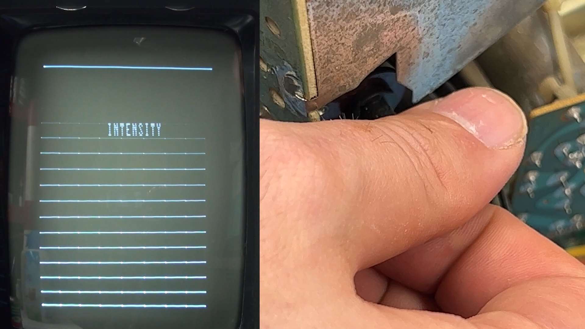
We're in the final stretch of screen calibration. The brightness control on the back can cause a lot of line artifacts as well as a bright dot in the center if it's too bright. But if it's too dim then you might not experience faint graphics in some games.
Once again turning to the test cart, there is a dedicated screen for adjusting the brightness. From this screen, the objective is to turn the brightness control so that the horizontal line that runs alongside the top of the word Intensity is just barely visible, and the ones above it should be invisible.
You can explore the other test screens at your leisure, but provided you've made the adjustments so far the rest should automatically be fine as-is. The focus test will show tiny gaps between each line in the center, while the outer ones blur together. Unless the entire yoke has become loose around the neck, the focus is locked in place.
Fixing Crackling Volume and Potentiometer Sensitivity Problems
The various internal and external potentiometers on the Vectrex including the volume control, brightness control and calibration controls are all subjectable to corrosion affecting their performance especially after so many years. It is very common for the volume control to crackle as you move it and be overly sensitive, and the brightness control can be impacted similarly. My go-to solution to fix any of these fader controls has been Deoxit Fader F5.
With the system unplugged, spray a burst of this in and around the affect control and then work it back and forward several times. If you're cleaning the volume control, you'll have to pull off the front knob first. Then spray one more burst and wait at least a few minutes for the solution to dry before powering the machine back on. You'll have to re-adjust any controls you clean in this manner.
There are times where the controls themselves might be beyond repair. I had this occur with a brightness adjust that was stuck on either full bright or absolute dark, and no amount of F5 resolved it. In those cases you'll need to do a repair using a new potentiometer of matching resistance.
Controller Repair
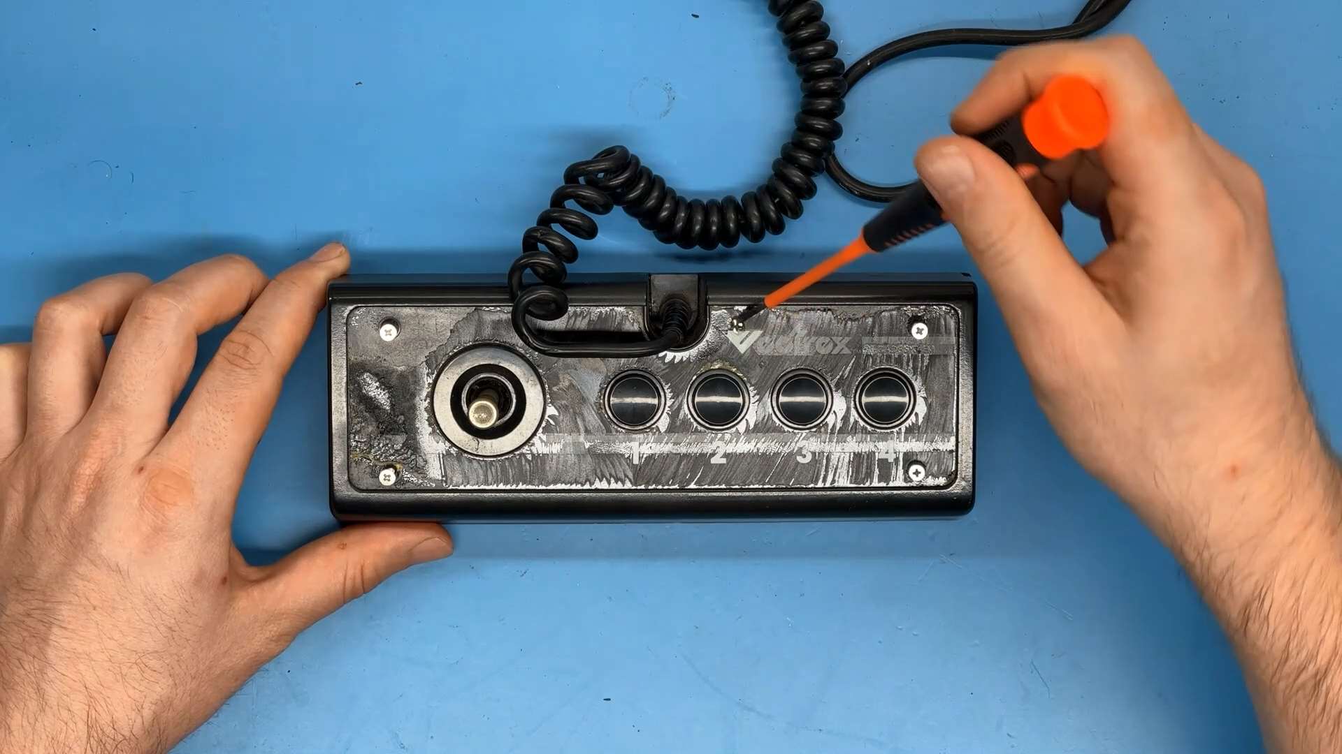
Original Vectrex controllers with pressure-sensitive analog sticks are becoming more expensive by the month. Although there are some third party alternatives, I'd advise against ones that have a digital-only directional stick as they can adversely impact gameplay on select games and weaken the overall experience.
Fortunately the controllers are easy enough to repair. If your controller has a continual drift even when the joystick recenters itself, or if the buttons are unresponsive or sticky, a simple internal cleaning and adjustment can help. Opening up the controllers requires removing hidden screws around the face plate. If you want to preserve the original sticker you'll have to use a heat-gun to slowly pry the edges away to reach the screws.
Once inside, gently clean the contacts under the buttons with Deoxit D100, D5 or Isopropyl Alcohol (IPA) and carefully wipe the rubber contacts with a lint free cloth.
Drifting can be remedied by adjusting the two internal pots and observing the changes on the screen, which is especially easy with the Test Cart Version 4 controller check.
If your joystick no longer returns to the center at all, a spring replacement is needed and can be ordered from Console5.com.
De-Buzzing Considerations
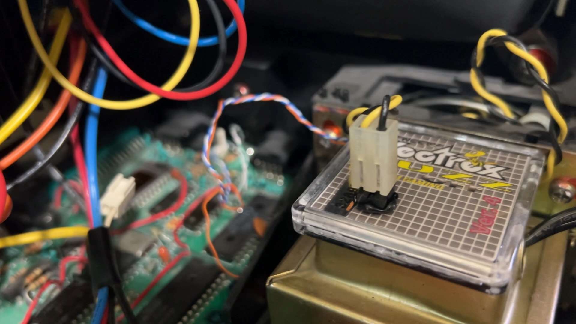
The buzz that emits from a Vectrex is a highly engaging topic. Some equate it with the true experience and nostalgia, while others prefer to de-buzz it so the crisp AY sound chip can shine. Gerry Karr, a Vectrex engineer, said their original in-house prototypes did not have this buzz.
There are many approaches to de-buzzing. I've implemented three different ones when experimenting including the coaxial mod, pre-amp reduction, and Obtanium Gaming's Buzz-Off package. Depending on your Vectrex's production run, these mods require varying levels of disassembly, soldering, cutting traces, and rerouting components or pinouts. You can find comparisons of these mods online.
In the video, you can hear the sound difference between an ordinary Vectrex with native buzz and one that has had the buzz-off mod integrated.
What’s Next? Ideas for Fun!
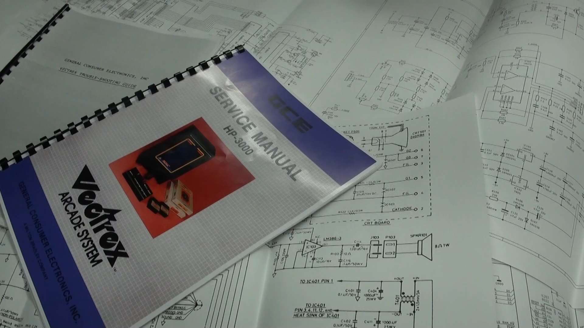
Hopefully your Vectrex is now running beautifully for many years to come. More advanced problems will need to be diagnosed deeper. For that I recommend the original service manual, schematics and troubleshooting guide as well as a new oscilloscope-friendly manual by Nicolas Weill. Even then repairing these systems can be an exercise in frustration especially if you're not exceedingly familiar with its hardware flow.
So what's next? The Vectrex fanbase is thriving and creative.
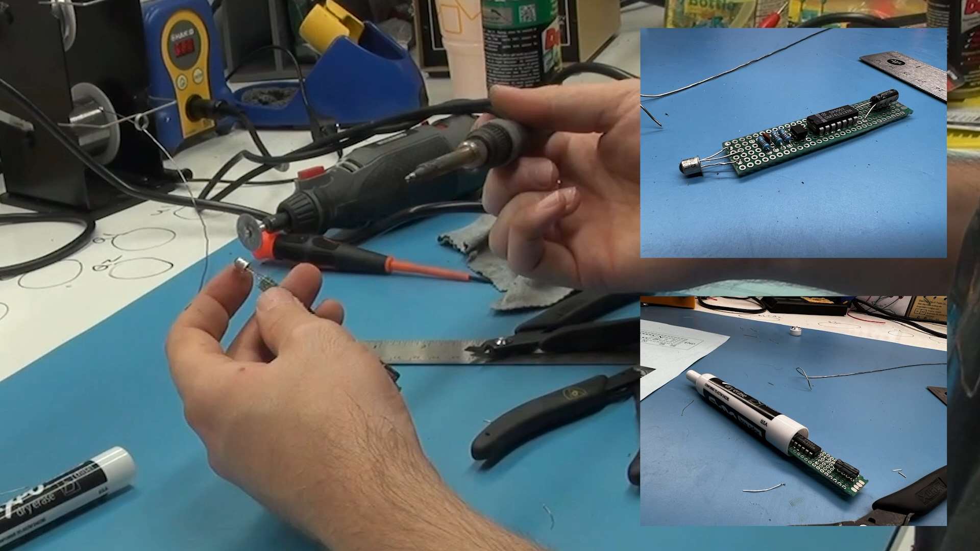
You can try your hand at making a homemade light pen.
Put a sweet vinyl wrap around the set like this synthetic woodgrain overload.
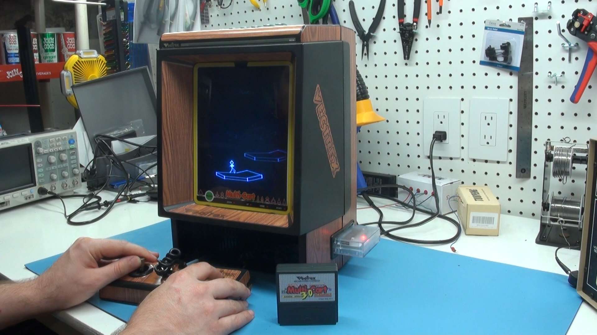
Grab a multicart and check out dozens of homebrew titles as well as the original game collection.
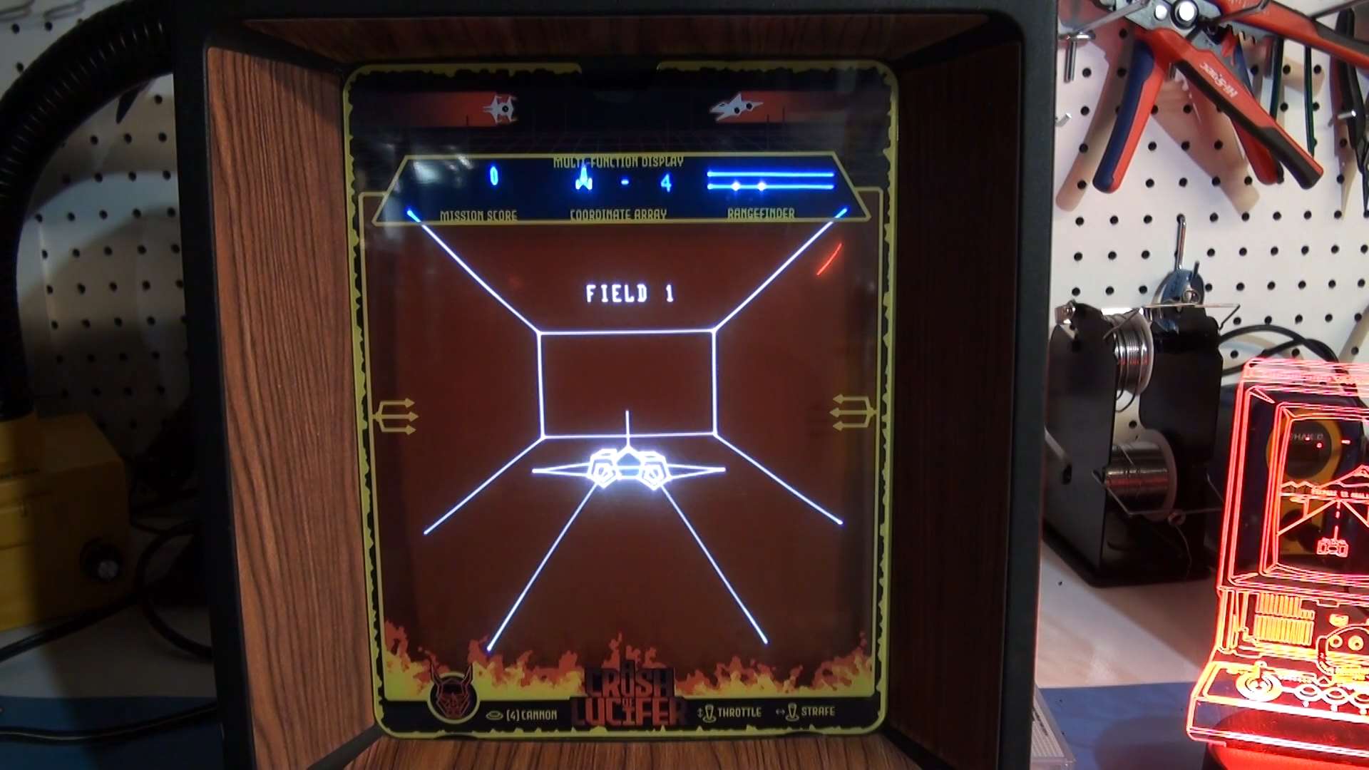
Immerse yourself in the recently released 1980s lost prototype: A Crush of Lucifer.
Or even start developing new titles or gadgets for it yourself!
I hope this guide has helped you out, any comments or questions please post below or at the YouTube video above.
















Hi Matt, very good guide, i have appreciated it.
Please i have a strange issue with my vectrex, i have found the 7905 fault in it and now the vector are designed on screen but, when system is cold all settings will be lost, the image are distorded, the test cart 4 intencity screen lines ar curved, the first test grid are not goor allineed.
I have checked al your pass in the guide, except the HV voltage, but the system is ok, not total ok, only when hot about after 1 hour, but if i make regulation when hot then i turn off for 30 minutes and then again on, the settings are lost again!
Can i have mode for send to you a photo if the issue ?
Thanks Emanuele