


(This article will serve as a compendium of knowledge about the incredibly elusive Cybervision 2001 system, for which few sites or articles exist online and no prior service manuals, schematics or reference materials have ever been published. This post will serve both as a well-documented exploration of my repair efforts, technical documentation, media details and more.)
I recently acquired the all-but-forgotten Cybervision 2001 (trademark stylized as "CyberVision 2001") , another late-70s attempt at breaching the home TV-hookup computer market. This system was sold exclusively in the Montgomery Ward catalog, and was featured prominently in a two-page opening spread in its 1978 Spring/Summer edition. The set sported the RCA 1802 CPU, 4K RAM and 1K ROM. The one I received is of multiple levels of despair and with little to no information, schematics and materials to go by online I figure I'll start a blog post to chronicle my experience. I will fill in with photos and/or videos in time.
Initial Observations and Overview
The set is housed in an all-wooden, blond-tone enclosure. This is unusual compared to the common plastic moldings seen in most systems from the era and gives it much more of a prototype feel than other sets I've worked on. It has a simple woodgrain inspired logo adhered to the front surface, a large volume control potentiometer, simple red power light indicator, and a mini push-button start/reset switch. These are all drilled and affixed directly to the otherwise plain wooden face, with the words VOL, ON and START stamped below them.
As was common at the time including with competing products like the Interact Home Computer, the top of the case included storage space for up to six data cassettes, or as the marketing referred to them — Cybersettes (a term which phonetically garners a very different sort of vision in modern times). The computer has a built-in cassette deck as the only means of data transfer, but sports a 2000 baud speed which was a feat for the time to make for rapid data access compared to the more common 300 baud counterparts. Perhaps most innovative is its use of a stereo head and internal speaker, so that each cassette program can playback studio quality cassette music and narration while simultaneously loading the application data into the computer. Internally the OS checks for a particular byte pattern when the data is loading to know when to stop or proceed, and through various uses of this functionality also enabled retrieving data in real-time off the cassette to continuously update the available 2K of data RAM.
There is a hardwired 12V AC power adapter in matching color, with the wires screwed into the face of the adapter. Initial power readings were around 14VAC without load, which was within specs but still inevitably worth replacing with a more modern 12V alternative for the longevity of the machine. The controllers are designated LEFT and RIGHT and are 40-key membrane style rectangles with A-Z, 0-9, ON, OFF, CLR and ENT buttons. Inside of the shell it is revealed the actual keypads are manufactured by Texas Instruments, not surprising considering they also carried a line of matching 40-key calculators at the time. They run down a ribbon cable and connect through two separate bulky ports on the back of the machine. I've seen more crude interfaces than these controllers, including the Bally Arcade which only had 24 calculator keys to input and program with. The controllers have a black plastic shell and are embossed with the CyberVision 2001 logo.
The system connects through ordinary RF into a black or white or colored television set. It has a fairly boilerplate tuner internally and you can also toggle between channel 3 and 4.
Basic Hardware Specs
- 1802 microprocessor
- 1K ROM
- 4K RAM (2K program memory and 2K video memory)
- 2000 Baud Two-Channel Cassette for Syncing Audio and Computer Data
- 128x96 Color Display
First Layer of Problems
Upon opening the case by removing the four screwed-in base stands, it was immediately observed that the tape belt had decayed over time and was severed. This is extremely common for cassette players from the 70s-80s. A makeshift solution is sometimes to use loom bands or similarly sized rubber bands, but long-term you'll want to replace with a comparable sized cassette belt widely available online. The broken one from the set measured around 25-26cm end-to-end, which would be around 8cm diameter belt. It's pretty easy to tell you have found the proper belt size replacement by playing a tape and listening for audio abnormalities as well as any tape eating symptoms indicative that the belt is not operating to spec.
I found several SRAM chips (P2101 - 256x4) were not well socketed and one was dislodged nearly in half, so reseated these. The RAM is arranged in four logical banks on the board, but I haven't even explored half the ICs yet so am still very unfamiliar with the overall logic board. Since no schematics or service manuals have been shared for this system, it's going to be a lot of manual review to figure out the workings.
There was one large electrolytic hanging off a terminal strip that bridged the cassette interface with the internal amplifier and logic board, I believe a 1000uF but will have to double-check. I replaced it with a new capacitor after poor readings from an ESR meter. Eventually I powered up the machine enough to review its baseline status. A corrupted version of the CyberVision logo appeared on the screen, which was a great indication that the most crucial components all were behaving fine including the CPU and ROM. I suspect there may be a few bad RAM sticks int here, though after manually shorting the reset wires the logo generally would clear up. Also, the reset switch itself was broken off internally, so will need to be swapped.
The cassette initially ate tapes I put in it, and after cleaning and re-adjusting the pinch roller and capstan as well as reworking the belt a bit, I was able to play a cassette to a reasonably decent level of quality and accuracy. But it didn't last long. Suddenly the magic smoke arose from a 22K resistor from the cassette circuit board. I am guessing 22K based on the three bands that weren't incinerated in the poof and checking other areas on the board to find comparably colored ones and then checking the four band color calculators online. I replaced that but another power-up revealed more smoke from the power area of the logic board. This time I discovered at least one if not several cracked rectifier diodes (WEP170) that make up the bridge rectifier labeled D1-D4 on the board, right near the AC power and large 2200uF capacitor. These diodes have specs of 2.5 Amp 1000V. Era accurate equivalents include HEP170, ECG125, R250. I don't have any 2+ Amp 1000V diodes in my toolbox at the moment so have some replacements on order.
When examining the cassette board closer, I noticed a couple of spliced together wires soldered to a pad that had lifted up along with some of the tracing. I followed the trace and added a bodge wire from the end point back to the spliced wires. Initially I was able to get the audio to play but eventually all I would get is a buzz regardless of playback. I diverted the audio out from the amp board to an auxiliary cable into a dedicated Bose system with similar symptoms, and likewise am not seemingly getting proper readings from the head itself. So this will need to be explored again once I have some more components on hand. I started replacing some of the caps on the cassette board, but there are many of them. The cassette component plugs into the logic board using two three-wire plugs (including ground). One plugs in near the AC power and supplies power to the cassette, while the other is labeled "TAPE TONE" and is where the actual data side of the cassette routes (the right channel). The audio side routes instead to an amplifier and then to the output speaker mounted inside the cabinet.
If I can get the main logic board back in operation, another experiment will be to wire up some feed directly to the input line on the logic board. If I'm ever able to read the data and load a program, that'd be a massive milestone even before fully fixing the cassette side of it. The cassettes themselves are rare and not archived anywhere online. I have a few that I am working to digitize in their true stereo format. Unfortunately my sound card and interface also suffered a malfunction in recent months so I am using work-arounds at the moment but have found success routing from a 1980s Panasonic stereo to my Focusrite 2i2.
A Note About Disassembly
Although it's easy enough to remove the wooden case by simply unscrewing the four rubber bases screwed in, it becomes a bit more tedious to get at the underside of the logic board. You will want to desolder the wires from the LED and reset switch (or from the board side) so that the wooden cabinet doesn't need to tag along. Then there are four bolts in each corner of the board that you can easily unscrew the nuts and washers using your fingers or a pliers. However, the board still won't come out. There are two 7805 voltage regulators on the underside of the board, riveted into the base case itself (originally a NEC 14305 and a NEC 7805H, TO-220-3L). The rivets need to be removed for these to release from the base. In my case a drill bit from inside out to remove the inner core, then a pliers to pull out the remnants of the rivet worked well. Even then, there's also a plastic riser tab in the center that you have to pop either out of the board or out of the case, again a pliers can be handy.
With all of the above taken care of and the two cassette connectors removed, you should be able to isolate the logic board to replace most components. The back accessories will still be connected so if you need absolute access to the underside of the board in ways that you can't manipulate with the peripheral connectors attached, some more work will be necessary. But I had no trouble propping the board up and even upside down with the back peripherals still affixed and could desolder and replace components easily.
Voltage Regulators, Revisited
The Cybervision 2001 uses two of the classic 7805 +5V voltage regulators. As mentioned, they are factory-riveted into steel base plate of the system. This is for good reason as these components are famous for getting blister-scorching hot in a matter of seconds if not properly cooled with an attached heatsink. These ones convert 12-14V input into 5V output.
Unfortunately the permenantly riveted solution makes the entire logic boar inaccessible for repairs. After drilling out the rivets, I found that using 6-32 x 1/2" machine screws with nuts made for an adequate and easily removable alternative. I applied new thermal paste to the base of the regulators before bolting them down.
In the process, I discovered one leg of the 7805 nearest the failed bridge rectifier circuitry was severed under the board. And the other had a loose solder connection on the unregulated-to-center-pin .1uF 12V ceramic cap. I removed both voltage regulators and even the one still in tact seemed brittle and was registering unusually on my multi-tester, so I exchanged both for new 7805s.
Without these regulators bolted down to the base, the heat build-up on these grows drastically fast. Within 5-10 seconds their thermal protection kicks on and immediately the output drops, simultaneously underpowering everything attached. If you're using a device that starts to exhibit strange video artifacts and loss, tearing or other symptoms it is always worth checking these sensitive voltage regulators and make sure the input and the output are steady and within spec.
Modern Alternatives
These days, several incredible drop-in replacements for 78xx series regulators exist. Through the use of buck converters or mini DC-DC adjustable output circuits, we can achieve the same result with much more reliability and none of the heat. Most of these replacements allow you to specify the output voltage anywhere from 1.8V through 12V and offer even greater flexibility with input voltage, so can be used for +5 and +12V rails common on vintage equipment. The sets boast an impressive 97% or higher efficiency rate.
I will be swapping the regulators with these modern counterparts after evaluating several different styles. This includes:
- R-78B5.0-1.5L (available via Digi-Key): Described as a Linear Regulator Replacement DC DC Converter 1 Output 5V 1.5A 6.5V - 18V Input this is a drop-in, pin-compatible replacement for the 78XX series linear regulators in a similar TO-220 form factor. At the time of this writing, they are $12.97 each, so considerably higher than a pack of 7805s but also a vast improvement.
- 78xx Replacement (SD8942) - This is a CC-BY-SA 3.0 replacement designed and shared by Stefan Wagner. It mimics the basic regulator style circuitry in the same footprint as a TO-220 linear, but uses a modern DC-DC converter IC. It supports variable voltage by soldering different resistors as detailed in the chart. A 5V converter typically uses a 110k and 15k resistor depending on the voltage reference (typically 0.6). The PCBs can be made via JLCPCB for under $10 for 30 of them using the provided design/Gerber, and I imagine that is similar via PCBWay. The majority of necessary surface mount components will already be in one's toolbox, and even the step down ICs are under $1.50 each. I look forward to constructing these as very cheap DIY converters.
- 5V Mini Voltage Reducer (example on Amazon): There are endless variants of this sort of component used largely in Arduino and DIY modern electronic projects. They are not form-fitting to be direct replacements for legacy regulators like the ones above are, but still have all the same options and pin-outs so can easily be worked into old projects as well. Most of them have adjustable (but fixed) voltage in similar ranges to the ones above. A 10 pack of these will cost around $12, not much more than a pack of 7805s.
Will update my findings in the future.
Cassette (Cybersette) Releases
A currently undetermined number of cassette tapes were released for the CyberVision 2001/3001. Original members of the Cybervision team indicate that "20 to over 40 titles" were released. I will be updating this section as I discover and catalog them. In my digitization efforts, I will also attempt to notate the timestamps of data and audio for further review and testing. A promotional interview announcing the system stated that "Wards is developing hundreds of these Cybersettes in many categories" and the initial catalog listing included 40 titles that were due for release in Jan-Mar 1978. Staff later acknowledged they overpromised and were unable to complete the magnitude of software titles anticipated.
The system used the LEFT CHANNEL for studio audio recordings that would playback through the internal speaker, and the RIGHT CHANNEL for 2000 baud data transfer that would feed directly into the logic board. Two separate connectors ran from the logic board to the cassette interface, one to feed the audio and the other to control power to the motor. This allows the system to programmatically stop the tape deck and wait for user input before continuing.
The listings of these titles gets more complicated as some changed titles or SKU numbers between 1978-1979 so appear differently in the few catalogs they appeared. Eventually this list will be better consolidated into a spreadsheet.
Introductory Series 1
This was the cassette that shipped with the Cybervision 2001 unit and included eight different activities.
Side A
- Application Selection Menu
- 1. Adjustments
- 2. Subchase
- 3. Biocycles
- 4. Meet the Meter
- 5. Flashy Fractions
- Adjustments
- Sub Chase
- Biocycles
- Math Madness: The Metric System ("Meet the Meter")
- Math Madness: Fractions ("Flashy Fractions")
Side B
- Designer
- Bulldozer
- Trivia
- Bedtime Story
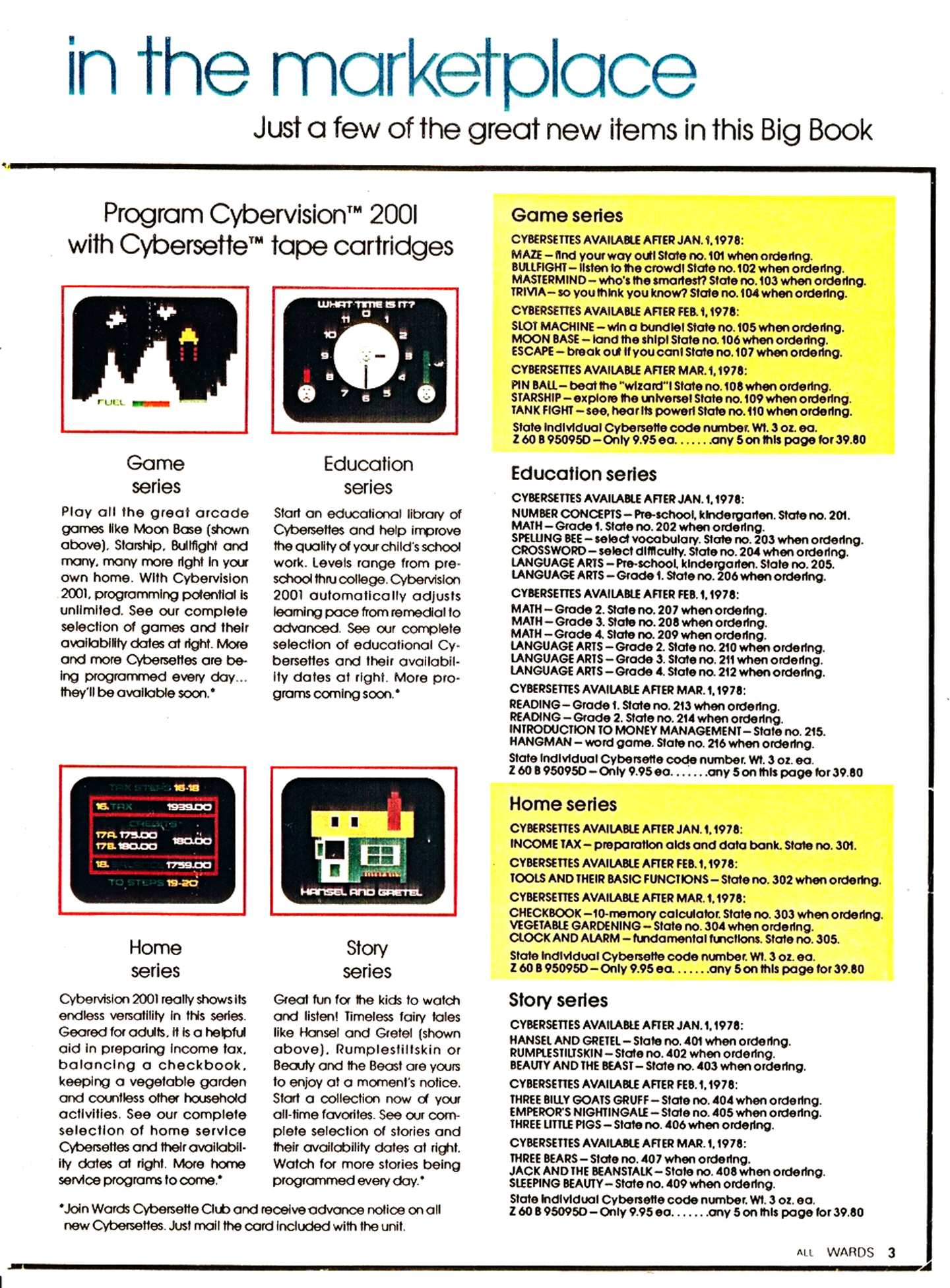
Game Series ($9.95 Each or 5/$39.80) - Montgomery Ward 1978-79 Catalogs
Cybersettes available after January 1, 1978:
- 101 - Maze: Find your way out!
- 102 - Bullfight: Listen to the crowd!
- 103 - Mastermind: Who's the smartest?
- 104 - Trivia: So you think you know?
Cybersettes available after Feb. 1, 1978:
- 105 - Slot Machine: Win a bundle!
- 106 - Moon Base: Land the ship!
- 107 - Escape: Break out if you can!
Cybersettes available after March 1, 1978:
- 108 - Pinball: Beat the "wizard!"
- 109 - Starship: Explore the universe!
- 110 - Tank Fight: See, hear its power!
Educational Series ($9.95 Each or 5/$39.80) - Montgomery Ward 1978-79 Catalogs
Cybersettes available after January 1, 1978:
- 201 - Number Concepts (Fish by Number): Pre-school, kindergarten. (Renamed to Fish by Number by 1979)
- 202 - Math: Grade 1.
- 203 - Spelling Bee: Select vocabulary.
- 204 - Crossword: Select difficult.
- 205 - Language Arts: Pre-school, kindergarten.
- 206 - Language Arts: Grade 1.
Cybersettes available after February 1, 1978:
- 207 - Math: Grade 2.
- 208 - Math: Grade 3.
- 209 - Math: Grade 4.
- 210 - Language Arts: Grade 2.
- 211 - Language Arts: Grade 3.
- 212 - Language Arts: Grade 4.
Cybersettes available after March 1, 1978:
- 213 - Reading: Grade 1.
- 214 - Reading: Grade 2.
- 215 - Introduction to Money Management.
- 216 - Hangman: Word game.
Home Series ($9.95 Each or 5/$39.80) - Montgomery Ward 1978 Catalog-79 Catalogs
Cybersettes available after January 1, 1978:
- 301 - Income Tax: Preparation aids and data bank.
Cybersettes available after February 1, 1978:
- 302 - Tools and Their Basic Functions.
Cybersettes available after March 1, 1978:
- 303 - Checkbook (Dollar Watch). 10-memory calculator. (Renamed to Dollar Watch by 1979)
- 304 - Vegetable Gardening.
- 305 - Clock and Alarm: Fundamental functions.
Story Series ($9.95 Each or 5/$39.80) - Montgomery Ward 1978 Catalog-79 Catalogs
Cybersettes available after January 1, 1978:
- 401 - Hansel and Gretel.
- 402 - Rumpelstiltskin.
- 403 - Beauty and the Beast.
Cybersettes available after February 1, 1978:
- 404 - Three Billy Goats Gruff.
- 405 - Emperor's Nightingale.
- 406 - Three Little Pigs.
Cybersettes available after March 1, 1978:
- 407 - Three Bears
- 408 - Jack and the Beanstalk
- 409 - Sleeping Beauty
Game Series ($16.95 Each) - Advertisement Listing
- 107 - Escape: Use your ingenuity!
- 108 - Star Flex: Beat the wizard!
- 104 - Trivia II: So you think you know the little things?
- 486 - Designer II: With scratchpad included.
Home Series ($16.95 Each) - Advertisement Listing
- 304 - Vegetable Gardening: Fundamentals in treatment and control.
- 484 - Address Organizer: Includes a scratchpad.
- 485 - Menu Organizer: Includes a scratchpad.
- 481 - Dollar Watch: Checkbook function. 10-memory calculator.
Educational Series ($14.95 Each) - Advertisement Listing
- 216 - Hangman: School days word game.
- 205 - One or More: Grade 1 grammar.
- 202 - Battleship: Grade school educational game.
- 204 - Crossword: Select difficulty.
- 213 - Mouse in My House: Grade 1 reading.
Story Series ($14.95 Each) - Advertisement Listing
- 405 - The Emperor's Nightingale
- 404 - Three Billy Goats Gruff
- 402 - Rumpelstiltskin
More on Cassette Reverse Engineering
The system ROM and programming logic reads particular data cues to stop or start playback. Upon hooking a scope up to the secondary connector that the cassette interface typically feeds into, the middle pin will read 0.5V high when powering the cassette and awaiting data. When the program needs to handle user input, a signal is sent that stops the current going to this pin and, in turn, powers off the cassette player.
This excerpt from Ken Balthaser's reflection via GameDeveloper.com seems very relevant here:
My single technical contribution, sort of, was the A5 synching system that we used. The CyberVision system used an off-the-shelf stereo cassette tape player for the data and soundtracks. The data was recorded on one track and the audio was recorded on the other. The system would load the data and begin executing the code while the audio played. A problem arose because there were slight differences in the motor speed for each tape deck. This meant that if a deck played back a little bit faster or slower then, after time the audio would get out of synch with the code.
That's when my experience in slide/sound productions came in handy. Multiple slide projectors were kept in synch or triggered to a sound track by using audio blips that would trigger the control box to change slides. I mentioned it to Joe as a possible solution to the synch problem. After some thought, he came up with a solution based on that type of system - A5's. The hexadecimal number A5 produces a unique series of bits as ones and zeros. By stringing a series of these A5's together the system would monitor the data track and “listen” for this unique series of bits. When it detected them, the computer would execute different commands such as stop tape, start tape, fast forward tape, etc.
Fast forwarding was another stroke of genius because this allowed code branching. This seems obvious and easy to do today with a gazillion gigabytes of RAM into which to load your code. But, back in 1977 the CyberVision had just 2K of RAM to work with. That meant, for example, if your code was 16K in size and you had just 2K to store it, you had to do something with the other 14K of code. Well, it was stored on the tape and loaded as needed. Brilliant!
(I am intrigued by Ken's remark about it also being able to control fast forward, which may be in error. My current understanding is that fast forwarding remains a semi-manual process, as explained below.)
General Lifecycle of Cassette Loading and Interactivity
The below sequence is my current understanding and confirmed functionality after a lot of experimentation, since documentation and cassette tapes are very scarce-to-non-existent.
- User inserts the cassette tape (Cybersette). Let's assume they also rewind it to the beginning.
- User powers on the Cybervision 2001 via power switch in back.
- User presses PLAY on the cassette player to begin reading the tape.
- The initial data loads a SELECTION MENU to choose from the available applications (usually 4-6 per 3o minute tape side).
- After the menu has loaded into memory, the data sends the aforementioned A5 series to DEACTIVATE THE CASSETTE POWER, which kills all playback instantly.
- A message appears advising the user to PRESS FAST FORWARD on the cassette player. This stops playback and prepares for FAST FORWARD operation, which won't do anything at this stage since the power to the cassette deck is disabled via the PCB/programming logic above.
- The user then presses the ON button on a controller, as advised.
- The menu selection appears on screen and awaits user input (by pressing the NUMBER corresponding to the program to load).
- On selection, the program REACTIVATES THE CASSETTE POWER to the cassette player for a particular amount of pre-programmed time. Since the user placed the cassette into FAST FORWARD mode, it will quickly begin spinning through the tape data.
- When the duration has elapsed, the system DEACTIVATES THE CASSETTE POWER once again. It has moved the cassette to an approximate location on the tape where the selected program data will begin.
- The user is instructed to press the PLAY button on the cassette and then press ON on their keypad, which once again begins playback and data loading.
- The chosen application itself now loads via the continued RIGHT channel data stream. Audio narration usually kicks on during this sequence as well, through the LEFT channel input.
- At various points throughout the program, the cassette interface power will be cut and restored to accommodate user input.
As I go through the cassette I've been testing (Introductory Series 1) I discover other things as I try to map particular datapoints and correlations to on-screen activity. You can actually begin loading any of the applications by beginning playback at their respective points. I found that a textual notice appears on screen 30 seconds and 15 seconds before the application data itself begins to load. This is a pretty clever and convenient way to give a heads up to the user how far away they are from the next application.
Also, if you attempt playback in the middle of data or in a way that clashes with the intended program behavior, a message will appear advising you to c.eck the tape. You then generally need to do a hard reset and begin again.
Cassette Data Feed, Sensitivity, Timing and Adjustments
At some point along my repairs I noticed that it grew a lot more difficult to pull in functional data reads no matter the volume, input source or base audio.
The right audio input signal feeds through a Bourns 3355 variable resistor (10k?), .01 cap among a few other connected components. It arrives into U26 (CD4098BE - CMOS Dual Monostable Multivibrator) via pin 14-15 (RxCx2 and Cx2). This all relates to timing and eventually reaches the channel 2 clock input, pin 11, of U25 (CD4013BE). And then finally this feeds into the A/B input of U24 (CD4034BE) which is what communicates with U22 (ROM) to parse the data.
I concluded the variable resistor had been rotated as part of some other prior work, and is extremely sensitive to the incoming data frequency. So even though it could be off quite a bit and still detect the opening cassette data transmission, it would fail after that.
Eventually I arrived at the sweet spot of 5.493K reading on the resistor. Which seems to load in data well without particular concern over original audio volume and I had success at 20%, 50%, 75% and 100% volume levels from my extracted audio tests.
Audio Amplifier
As I begin diagnosing the cassette deck itself, which previously went up into various puffs of smoke, the easiest point to start with is the audio amplifier itself. This is a self-contained PCB stamped 1215 AUDIO AMP. Currently the issue seems there are no volts getting to it from the maze of cassette deck PCB components. I have verified that the tape head is operational and can hear faint audio directly from those components, but it falls off by the time it reaches the terminal strip with large capacitor, which is what in turn runs into the amp PCB.
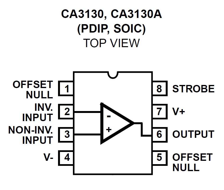
The heart of the amplifier is the 8-pin CA3130E op-amp. Wires feed into this from the volume potentiometer ("IN"), internal speaker +/- (SPKR), and two lines from the terminal resistor mounted to the cassette deck itself (+ / -). On this chip, pins 4 + 7 correspond to V- and V+, pins 2-3 for NON-INV and INV input, and 6 for OUTPUT.
- PIN 2 (INV. INPUT) is tied to the IN wire from potentiometer.
- PIN 4 (V-) is tied to the SPKR - as well as the negative (-) input wire.
- PIN 6 (OUTPUT) runs to the base of both transistors.
- PIN 7 (V+) is tied to the positive (+) input wire and loops to PIN 3 (NON INV. INPUT)


ID | Component | Description |
|---|---|---|
C101 | Electrolytic Cap | 100uF 10V |
C102 | Electrolytic Cap | 100uF 10V |
C103 | Ceramic Cap | 181K (180pF 1KV +/- 10%) |
C104 | Ceramic Cap | .05 +80 -20 12V |
C105 | Ceramic Cap | 1KV S3N (100 pF ±10% 1000V) |
Q101 | Transistor | 2N3904 NPN |
Q102 | Transistor | 2N3906 PNP |
R101 | Resistor | 4.7k Ohms 5% |
R102 | Resistor | 22k Ohms 5% |
R103 | Resistor | 150k Ohms 5% |
R104 | Resistor | 22k Ohms 5% Resistor |
U1 | Op Amp | CA3130E |
Controller Problems and Analysis
After wrestling with the cassette interfacing and creating my own hardwired aux in for testing, I discovered various controller malfunctions. Both the LEFT and RIGHT controllers are said to be usable interchangeably and in most instances this appears to be correct. But I discovered that certain buttons on certain controllers just were not working. The keypad is arranged in a 5x8 matrix.
Controller Pin-Out
Each controller has a 13 wire ribbon connector running into a large 24-pin male connector, that plugs into matched female sockets on the enclosure. The connectors are branded Burndy, which to this day remains a large connector manufacturer. A little scrounging around on connector part websites, and I found the actual part numbers for both the plug and the socket!
- 70 7156-00 - Connector, 24 Pin Plug - Burndy SMS24P-1 (51-406580)
- 70 7157-00 - Connector, 24 Pin Socket - Burndy SMS24R-1 (51-406581)
These can still at least be somewhat found on sites like Mouser and eBay, and here's a site that also contains a catalog/datasheet and more details. Knowing what sockets it used is helpful, and they also seem to be reasonable candidates for 3D printing as well.
The wires feed into the following pin holes attached to the controller, as labeled:
- PIN 1: Brown - Tied to both ports
- PIN 2: Red - Tied to both ports
- PIN 3: Orange - Tied to both ports
- PIN 4: Yellow - Tied to both ports
- PIN 5: Green - Tied to both ports
- PIN 6: Blue #1 - Tied to both ports
- PIN 7: Purple #1 - Tied to both ports
- PIN 8: Gray #1 - Tied to both ports
- PIN 17: Blue #2 - Tied to PIN 15
- PIN 21: White - Tied to PIN 15
- PIN 22: Gray #2 - Tied to PIN 15
- PIN 23: Purple #2 - Tied to PIN 15
- PIN 24: Black - Tied to PIN 15
The LEFT controller port feeds into the RIGHT controller port at the socket level. The RIGHT controller port then feeds into the top-right of the logic board when viewed from above. They used rubber/sealant glue around all of the controller pin connectors going into the PCB to help against wear and tear. I removed all of that to make the wires more visible and repaired a few broken lines.
The RIGHT controller port has two additional pins, which supplies it +5V from the board (and in turn, supplies the +5V feed for the five pins that correspond to the five columns).
- PIN 14: White (Positive 5V)
- PIN 15: Black (Negative 5V)
Motherboard Connections
When looking at the board from above and beginning with the leftmost controller-related pin, the ordering on the PCB contains 21 wires between the sockets and is arranged as follows:
+5V Line
- PIN 1: Black (From PIN 15 of RIGHT Controller) Negative Lead to +5V
- PIN 2: White (From PIN 14 of RIGHT Controller) Positive Lead to +5V
8 Keypad Rows
- PIN 3: Gray (From PIN 8 of RIGHT Controller, tied to LEFT)
- PIN 4: Purple (From PIN 7 of RIGHT Controller, tied to LEFT)
- PIN 5: Blue (From PIN 6 of RIGHT Controller, tied to LEFT)
- PIN 6: Green (From PIN 5 of RIGHT Controller, tied to LEFT)
- PIN 7: Yellow (From PIN 4 of RIGHT Controller, tied to LEFT)
- PIN 8: Orange (From PIN 3 of RIGHT Controller, tied to LEFT)
- PIN 9: Red (From PIN 2 of RIGHT Controller, tied to LEFT)
- Pin 10: Brown (From PIN 1 of RIGHT Controller, tied to LEFT)
5 LEFT Controller Keypad Columns (Tied to +5V Line)
- PIN 11: Black (from PIN 24 of LEFT Controller)
- PIN 12: White (from PIN 21 of LEFT Controller)
- PIN 13: Gray (from PIN 22 of LEFT Controller)
- PIN 14: Purple (from PIN 23 of LEFT Controller)
- PIN 15: Blue (from PIN 17 of LEFT Controller)
5 RIGHT Controller Keypad Columns (Tied to +5V Line)
- PIN 16: Green (From PIN 24 of RIGHT Controller)
- PIN 17: Yellow (From PIN 21 of RIGHT Controller)
- PIN 18: Orange (From PIN 22 of RIGHT Controller)
- PIN 19: Red (From PIN 23 of RIGHT Controller)
- PIN 20: Brown (From PIN 17 of RIGHT Controller)
In this process, I discovered one additional wire lead (PIN 19) had torn out so resoldered that. Hooked to an oscilloscope, the following PCB pins have been mapped out as supplying voltage on keypress:
- PIN 3: 7, 8, 9, U, V
- PIN 4: 4, 5, 6, W, X
- PIN 5: 1, 2, 3, Y, Z
- PIN 6: ON, 0, OFF, CLR, ENT
- PIN 7: P, Q, R, S, T
- PIN 8: K, L, M, N, O
- PIN 9: F, G, H, I, J
- PIN 10: A, B, C, D, E
The RIGHT controller was unable to ever get input from the middle column (OFF, R, M, H, C, 3, 6, 9). The LEFT controller seemed to have failure for U, and intermittent problems with C and D. I did swap one controller to an alternative one to try and rule that out but will do a little further testing on that front. (Update: I found the bad column was confined to a single controller.) I also reflowed all the solder points of the wires feeding into the PCB.
Pins 3-10 above feed into a 16-pin IC U58, CD4532BE RCA 823 - CMOS 8-Bit Priority Encoder. This translates the data into a 3-bit output (Q0, Q1, Q2) based on each pin's high or low state.
- PIN 3 wire to PIN 1 IC (D4)
- PIN 4 wire to PIN PIN 2 IC (D5)
- PIN 5 wire to PIN 3 IC (D6)
- PIN 6 wire to PIN 4 IC (D7)
- PIN 7 wire to PIN 13 IC (D3)
- PIN 8 wire to PIN 12 IC (D2)
- PIN 9 wire to PIN 11 IC (D1)
- PIN 10 wire to PIN 10 IC (D0)
That output is sent down to U3, one of the four CDP18520 I/O chips (DI0, DI1, DI2).
The cluster of 2N5365 transistors feeds the five wires correlating to the five columns from each keypad matrix. The state of these filter to a final five points that get fed into the same U3 via DI3, DI4, DI5, DI6, DI7. So the final passed byte can be interpreted by U3 and the ROM to pinpoint exactly what key has been pressed.
- PIN 11 wire to Q12 base
- PIN 12 wire to Q15 base
- PIN 13 wire to Q14 base
- PIN 14 wire to Q13 bases
- PIN 15 wire to Q12 emitter
- PIN 16 wire to Q8 base (collector runs to Q12 collector)
- PIN 17 wire to Q11 base (collector runs to Q15 collector)
- PIN 18 wire to Q20 base (collector runs to Q14 collector)
- PIN 19 wire to Q9 base (collector runs to Q13 collector)
PIN 15 wire also feeds into U88, continuity to pin 5, 6, 7, 8, 9, 14, 16.
The truth table of this arrangement, from the datasheet, is below.
Initially, none of the buttons actually respond to any on-screen input. But I have verified that the majority of them do in fact reach the PCB, so I will have to follow it up the traces from there.
2/11/2023 Update: After more testing and inspection of the transistors, I pinpointed the culprit to Q15 that had a short between the base and collector. This was resulting in a stuck +5V and overriding any other keypresses. I replaced the transistor with an A1015 that I had on hand, and now both controllers work well!
3/23/2023 Update: The keyboard wires running into the motherboard are very fragile. They are just thin stranded wires hard-soldered into points on the logic board. Due to the way the board itself has to be lifted for desoldering and repairs, the wires tear easily. This has been a continual problem throughout the process. My makeshift solution was to add pin headers to each of the keypad solder points on the logic board, and then add quick connect female jumper wire ends to the keypad wiring. I used heatshrink to ensure each is insulated from another, and then was able to replace them on the board. This makes it possible to remove or replace the wires on-the-fly and also gives them a lot more stability than the previous arrangement. It is similar to the process I used on my TRS-80 Model 1 restore by replacing the failing ribbon cable with pin headers and a standard IDE cable.
Integrated Circuit ICs U1-U89
There are 89 identified ICs on the board (plus two more 7805 regulators affixed to the base). I was impressed on first review that every single chip has a socket, which is unlike many other systems I have had to repair where the chips are all hard-soldered into the PCB for cost savings or low profile reasons. I have done a fairly complete audit of them by this point.
Most of the ICs are bog standard (gates, registers, decoders, encoders...) A few notable bits (full table below):
- U6-U21, U41-U56: 22-pin 2101 NMOS 256 x 4-bit RAM (a.k.a. 4101, 5101, 9101, AMD 93422, TC5501P). There are four 8 chip banks for RAM on the board, totaling 4K of available RAM (2K data, 2K video). There are some third party 5101 RAM testers out there but largely discontinued, but I'll keep searching for one as I suspect there is some corruption going on in the VRAM that takes multiple resets to straighten up.
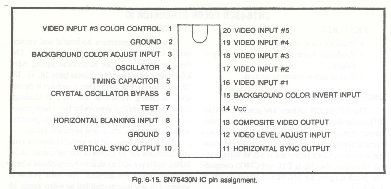
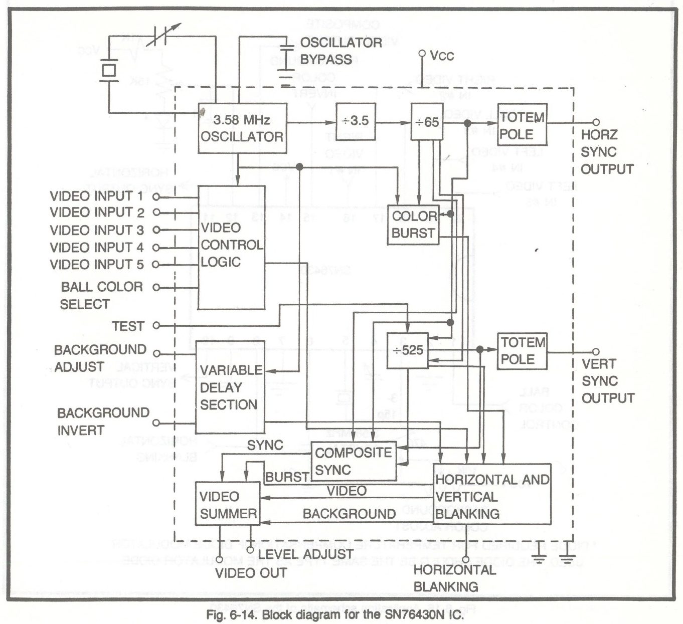
- U80:20-Pin SN76430N Sync Generator / Color Generator / Video Summing. This is a proprietary TI game chip that handles all of the video output. Very scant information about it including any datasheets, but I found one reference to it in a 1978 repair book that shows a lot of promise. More on that in another section.
- U22: CDP1834 1024-Word X 8-Bit Static ROM. This is the all-important ROM operating system / firmware that makes the system work. It is pin-compatible with the 2708 EPROM. I am currently awaiting parts to build a 2708 dumper since even my several vintage EPROM programmers don't support it, and the one that does is out of commission. The OS displays "Cybervision" and awaits cassette playback to load into RAM and communicate with the CPU.
- U24: CD4034B 8-Stage Bidirectional Parallel/Serial Input/Output Bus Register. This goes hand-in-hand with the U22 ROM to actually read and interpret the incoming/outgoing cassette data. With this chip removed, no data is readable and you will get a CHECK TAPE error. I assume this IC plays an important roll in also stopping and starting the tape playback but have not done any analysis yet.
U | Component | Description | Pins | OG Part | Datasheet | Notes |
|---|---|---|---|---|---|---|
1 | RCA 1802 | CPU | 40 | CDP1802 | ||
2 | CDP1852 | Byte-Wide Input/Output Port | 24 | CDP1852D | ||
3 | CDP1852 | Byte-Wide Input/Output Port | 24 | CDP1852D | ||
4 | CDP1852 | Byte-Wide Input/Output Port | 24 | CDP1852D | ||
5 | CDP1852 | Byte-Wide Input/Output Port | 24 | CDP1852D | ||
6 | P2101 | 256 X 4 STANDARD SRAM | 22 | P2101-1 | ||
7 | P2101 | 256 X 4 STANDARD SRAM | 22 | P2101-1 | ||
8 | P2101 | 256 X 4 STANDARD SRAM | 22 | P2101-1 | ||
9 | P2101 | 256 X 4 STANDARD SRAM | 22 | P2101-1 | ||
10 | P2101 | 256 X 4 STANDARD SRAM | 22 | P2101-1 | ||
11 | P2101 | 256 X 4 STANDARD SRAM | 22 | P2101-1 | ||
12 | P2101 | 256 X 4 STANDARD SRAM | 22 | P2101-1 | ||
13 | P2101 | 256 X 4 STANDARD SRAM | 22 | P2101-1 | ||
14 | P2101 | 256 X 4 STANDARD SRAM | 22 | P2101-1 | ||
15 | P2101 | 256 X 4 STANDARD SRAM | 22 | P2101-1 | ||
16 | P2101 | 256 X 4 STANDARD SRAM | 22 | P2101-1 | ||
17 | P2101 | 256 X 4 STANDARD SRAM | 22 | P2101-1 | ||
18 | P2101 | 256 X 4 STANDARD SRAM | 22 | P2101-1 | ||
19 | P2101 | 256 X 4 STANDARD SRAM | 22 | P2101-1 | ||
20 | P2101 | 256 X 4 STANDARD SRAM | 22 | P2101-1 | ||
21 | P2101 | 256 X 4 STANDARD SRAM | 22 | P2101-1 | ||
22 | CDP1834 | 1028-Word X 8-Bit Static ROM | 24 | CDP1834CE | Operating System ROM |
|
23 | CD4098B | CMOS Dual Monostable Multivibrator | 16 | CD4098BE | ||
24 | CD4034B | 8-Stage TRI-STATE Bidirectional Parallel/Serial Input/Output Bus Register | 24 | CD4034BE | Companion to OS ROM |
|
25 | CD4013B | CMOS Dual D-Type Flip-Flop | 14 | CD4013BE | ||
26 | CD4098B | CMOS Dual Monostable Multivibrator | 16 | CD4098BE | ||
27 | CA3130 | 15MHz BiMOS Operational AMplifier with MOSFET Input-CMOS Output | 8 | CA3130E | ||
28 | CD4013B | CMOS NAND Gate | 14 | CD4013BE | ||
29 | MC14018B | Presettable Divide-By-N Counter | 16 | MC14018B | ||
30 | CD4024B | CMOS Ripple-Carry Binary Counter/Dividers | 14 | CD4024BE | ||
31 | CD4013B | CMOS NAND Gate | 14 | CD4013BE | ||
32 | CD4013B | CMOS NAND Gate | 14 | CD4013BE | ||
33 | CD4021A | CMOS 8-Stage Static Shift Register | 16 | CD4021AE | ||
34 | CD4001 | CMOS Quad 2-Input NOR Gate | 14 | CD4001UBE | ||
35 | CD4011B | CMOS NAND Gate | 14 | CD4011BE | ||
36 | CD4069UB | CMOS Hex Inverter | 14 | CD4069UBE | ||
37 | CD4011B | CMOS NAND Gate | 14 | CD4011BE | ||
38 | CD4069UB | CMOS Hex Inverter | 14 | CD4069UBE | ||
39 | 7805 (LM340) | Fixed Voltage Regulator | 3 | LM340-5 | ||
40 | CD4555B | CMOS Dual Binary to 1 of 4 Decoder/Demultiplexers | 16 | CD4555BE | ||
41 | P2101 | 256 X 4 STANDARD SRAM | 22 | P2101-1 | ||
42 | P2101 | 256 X 4 STANDARD SRAM | 22 | P2101-1 | ||
43 | P2101 | 256 X 4 STANDARD SRAM | 22 | P2101-1 | ||
44 | P2101 | 256 X 4 STANDARD SRAM | 22 | P2101-1 | ||
45 | P2101 | 256 X 4 STANDARD SRAM | 22 | P2101-1 | ||
46 | P2101 | 256 X 4 STANDARD SRAM | 22 | P2101-1 | ||
47 | P2101 | 256 X 4 STANDARD SRAM | 22 | P2101-1 | ||
48 | P2101 | 256 X 4 STANDARD SRAM | 22 | P2101-1 | ||
49 | P2101 | 256 X 4 STANDARD SRAM | 22 | P2101-1 | ||
50 | P2101 | 256 X 4 STANDARD SRAM | 22 | P2101-1 | ||
51 | P2101 | 256 X 4 STANDARD SRAM | 22 | P2101-1 | ||
52 | P2101 | 256 X 4 STANDARD SRAM | 22 | P2101-1 | ||
53 | P2101 | 256 X 4 STANDARD SRAM | 22 | P2101-1 | ||
54 | P2101 | 256 X 4 STANDARD SRAM | 22 | P2101-1 | ||
55 | P2101 | 256 X 4 STANDARD SRAM | 22 | P2101-1 | ||
56 | P2101 | 256 X 4 STANDARD SRAM | 22 | P2101-1 | ||
57 | CD4066B | CMOS Quad Bilateral Switch | 14 | CD4066BE | ||
58 | CD4532B | CMOS 8-Bit Priority Encoder | 14 | CD4532BE | Controller Keypad Encoder |
|
59 | CD4081B | CMOS AND Gate | 14 | CD4081BE | ||
60 | CD4555B | CMOS Dual Binary to 1 of 4 Decoder/Demultiplexers | 16 | CD4555BE | ||
61 | CD4019B | CMOS Quad AND/OR Select Gate | 16 | CD4019BE | ||
62 | CD4019B | CMOS Quad AND/OR Select Gate | 16 | CD4019BE | ||
63 | CD4019B | CMOS Quad AND/OR Select Gate | 16 | CD4019BE | ||
64 | 4404B | CMOS 8-Stage Binary Counter | 14 | SCL4404BE | ||
65 | CD4024B | CMOS Ripple-Carry Binary Counter/Dividers | 14 | CD4024BE | ||
66 | CD4024B | CMOS Ripple-Carry Binary Counter/Dividers | 14 | CD4024BE | ||
67 | CD4024B | CMOS Ripple-Carry Binary Counter/Dividers | 14 | CD4024BE | ||
68 | CD4001 | CMOS Quad 2-Input NOR Gate | 14 | CD4001UBE | ||
69 | CD4076B | CMOS 4-Bit D-Type Registers | 16 | CD4076BE | ||
70 | CD4076B | CMOS 4-Bit D-Type Registers | 16 | CD4076BE | ||
71 | CD4019B | CMOS Quad AND/OR Select Gate | 16 | CD4019BE | ||
72 | CD4555B | CMOS Dual Binary to 1 of 4 Decoder/Demultiplexers | 16 | CD4555BE | ||
73 | CD4066B | CMOS Quad Bilateral Switch | 14 | CD4066BE | ||
74 | CD4013B | CMOS NAND Gate | 14 | CD4013BE | ||
75 | CD4013B | CMOS NAND Gate | 14 | CD4013BE | ||
76 | CD4066B | CMOS Quad Bilateral Switch | 14 | CD4066BE | ||
77 | CD4066B | CMOS Quad Bilateral Switch | 14 | CD4066BE | ||
78 | CD409UB | CMOS Hex Inverting Buffer and Converter | 16 | CD4049UBE | ||
79 | CD4069UB | CMOS Hex Inverter | 14 | CD4069UBE | ||
80 | SN76430N | Sync Generator / Color Generator / Video Summing | 20 | SN76430N | Video Generator |
|
81 | CD4024B | CMOS Ripple-Carry Binary Counter/Dividers | 14 | CD4024BE | ||
82 | MC14018B | Presettable Divide-By-N Counter | 16 | MC14018B | ||
83 | CD4007UB | CMOS Dual Complementary Pair Plus Inverter | 14 | CD4007UBE | ||
84 | CD4046B | CMOS Micropower Phase-Locked Loop | 16 | CD4046BE | ||
85 | CD4069UB | CMOS Hex Inverter | 14 | CD4069UBE | ||
86 | CD4001UB | CMOS Quad 2-Input NOR Gate | 14 | CD4001UBE | ||
87 | CD4001C | CMOS Quad 2-Input NOR Gate | 14 | CD4001CN | ||
88 | CD4532B | CMOS 8-Bit Priority Encoder | 16 | CD4532BE | ||
89 | CD4069UB | CMOS Hex Inverter | 14 | CD4069UBE | ||
90 | 7805 (LM340) | Fixed Voltage Regulator | 3 | NEC 14305 | Riveted from underneath PCB to metal base. |
|
91 | 7805 (LM340) | Fixed Voltage Regulator | 3 | NEC 7805H | Riveted from underneath PCB to metal base. |
SN76430N Sync and Video Generator
The most elusive of all ICs on the board is the TI SN76430N. You'll find very few references to it online and no dedicated datasheet. However, some digging around via archive.org and I found a couple sources that mentioned it and other proprietary TI game chips.

An advertisement in an issue of CQ Elettronica (Spanish) included a rundown of TI game chips. The list is fascinating as it offers a glimpse into a hobbyist and commercialized era where entire dedicated chips were used to perform hyper-specialized functions like "Scoring" and "Gun Fighter / Universal Man Characters" and "Exploding Helicopter Character." So many of these chips are no longer obtainable and/or have such little documentation it becomes a real effort to determine how to interface with them.
This research led me to happen upon another graciously digitized book called "How to Repair Video Games" by Robert Goodman. It is from 1978, the same year as the Cybervision. The book offers some very sound advice for all kinds of electronics of the time including dedicated sections on Radio Shack TV Scoreboard Games, Magnovox Odyssey TV Video Games, RCA Studio II, General Instrument Game Chips, Texas Instrument Game Chips, National Semiconductor Video Game System, Atari Pong and Midway Home Pinball Games. Nestled among the 255 pages is a multi-page entry for the SN76430N.
FEATURES
- Provides color composite video signal.
- Produces horizontal and vertical sync pulses.
- Built-in video summing section.
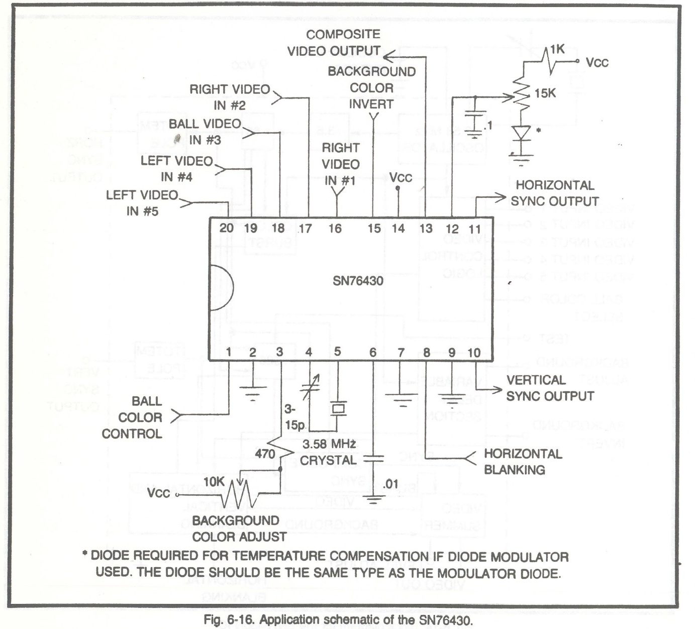
CIRCUIT DESCRIPTION
The SN76430N utilizes low-power Schottky TTL technology to provide a color composite video output signal, video summing, and horizontal and vertical synchronization pulses in a complete video game system. Clock reference is a 3.58 MHz crystal. Of course, the chip is TTL and CMOS compatible.
IC OPERATION
The circuit generates horizontal and vertical sync pulses from a 3.58 MHz internal oscillator. The chip also contains a video summer accepting video information from five video inputs (pins 16, 17, 18, 19, and 20). A composite video waveform is generated containing horizontal and vertical blanking, horizontal and vertical sync, color burst background video information, spot video information (players, walls, balls, score, etc.), and serration pulses.
Color burst begins at the end of horizontal sync and continues for 14 cycles of the subcarrier (3.58 MHz), and is present on all lines except those where serration pulses are present. The color yellow is assigned to any information fed to video inputs 16 and 17. The color phase is the same as burst. Light-blue color is assigned to any information fed to video input pins 19 and 20. The information fed to pin 18 is yellow when pin 1 is a logic zero, matching the yellow assigned to pins 16 and 17. When pin 1 is switched to a logic one, the information at 18 is changed to the light-blue color, matching the light-blue color assigned to pins 19 and 20.
Background color is adjustable by raising or lowering the DC level into pin 3, with an adjustment of about 180° possible. A background color inversion of 195° from pin 3 setting may be obtained by applying a logic one to the background color invert pin (pin 15).
Horizontal and vertical sync outputs are totem-pole type, and compatible with standard TTL and CMOS circuits. Horizontal sync pulse width is approximately 4.85 μs. Vertical sync pulse width is three horizontal sync pulses. Vertical blanking begins 3 horizontal lines before vertical sync, and continues for 19 horizontal lines. Horizontal blanking (generated externally, and applied at pin 8) and vertical blanking will eliminate video signals, excluding burst. The fact that it purportedly generates simple composite out makes for an inviting prospect toward composite modding the set once it's operational again.
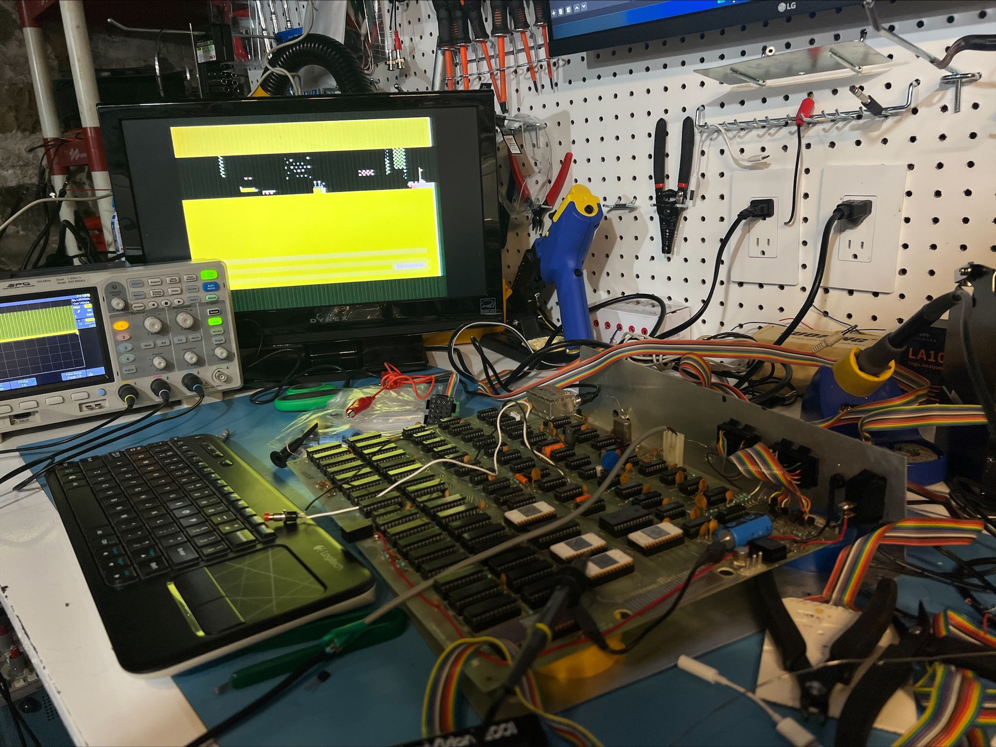
Logic Board Layout
Below are images I snapped of the front and back of the logic board during my repair efforts. They are relatively aligned but not every component is fully visible. I took these mostly for my personal reference in tracing paths, and they have proven very useful at that. The board is very neatly laid out on double layer PCB. Beyond the 89 ICs there aren't a tremendous amount of other components. It is easiest to save both images and flip back and forth or hide/show layers in an editing app to trace the circuits. Before I reassemble the item I will attempt to take higher resolution photos, but these are generally okay as-is.
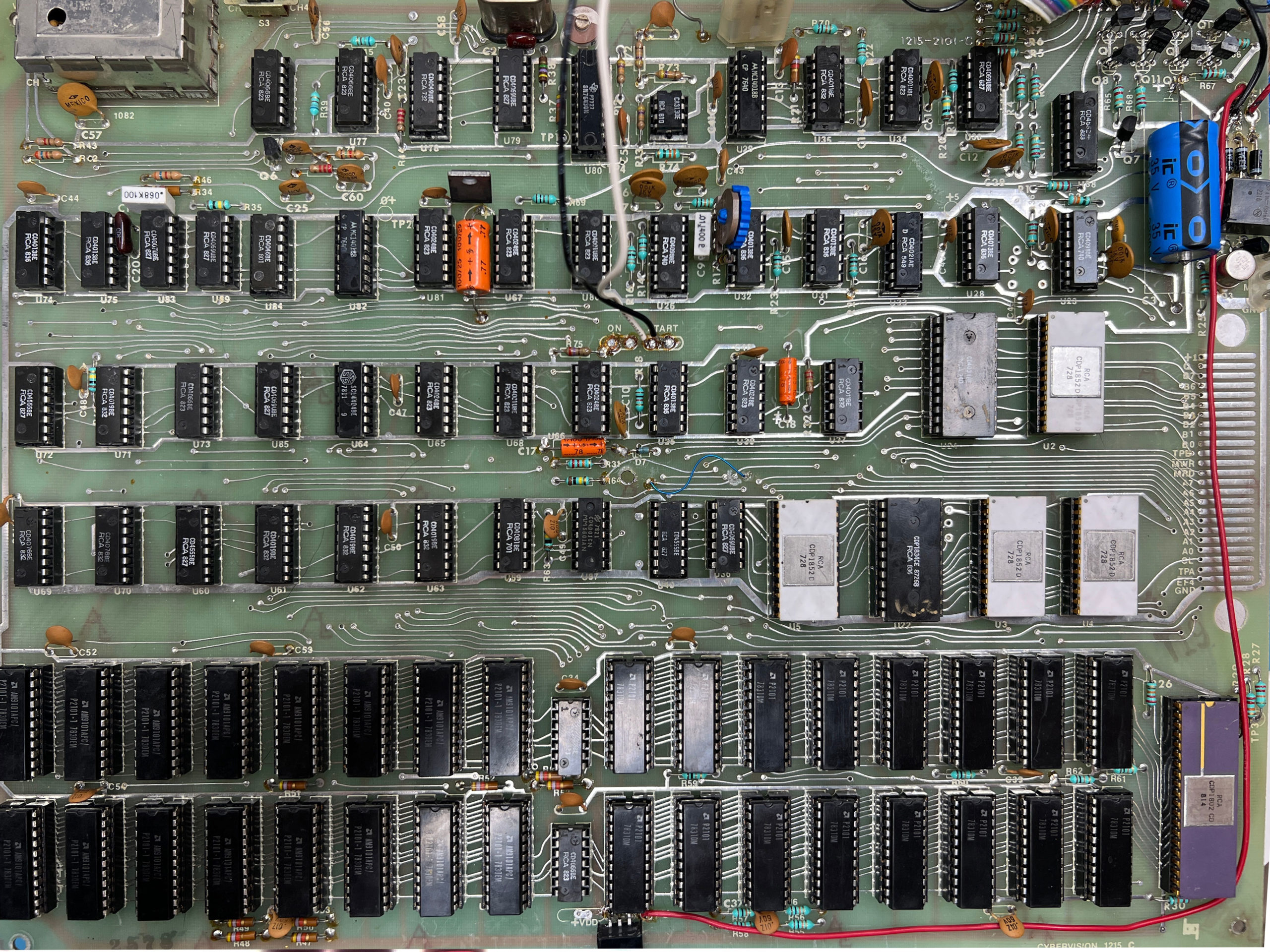
Cybervision 2001 logic board (front)

Cybervision 2001 logic board (back)
A Second Wave of Problems
(This section was added on March 2, 2023.)
While all was going well for a long time, an unfortunate incident occurred when I was working at troubleshooting the cassette deck. It wound up making contact with the logic board while the system was running. This instantly led to a garbage screen of artifacts that unfortunately persists.
I began checking the various components with both a multimeter and scope. Of concern are the output lines of the ROM (U22) tied to the CPU (U1) where I am seeing both garbled data and at least one output line (Q5) apparently stuck on high. Further, the middle prong of the cassette interface is stuck at 1-2V instead of the steady 4.5+V it should be when the system first boots. Other voltages including on the RAM check out.
Removing the ROM has no visible change, and my hope is that the ROM itself did not suffer any corruption and that the anomalies I see are from somewhere upstream. I was working to build a 2708 EPROM programmer but hadn't gotten it done prior to this problem.
I have tested a few transistors and swapped the RAM around as well as cleaned the sockets to all ICs. Another observation is that there appears to be voltage leaking through to the components even when the switch is turned off. In fact the switch itself was also misbehaving and warrants replacing. So I will probably take a closer look at the bridge rectifier section and switch. Thankfully, replacement switches are readily available. Switch Rocker 10A, 125V SPST Panel Mount Quick Connector, Alco, LR-9280. The one included in the CyberVision has the topmost pin broken out. Then half of the 12V AC power cord connects to prong 2, and the other half to the logic board that is bridged by a wire running from prong 3.
ROM Dump (Spoiler: It Is Corrupted)
(This section was added on March 2, 2023 and revised on March 4, 2023, March 22, 2023.)
For many years the Cybervision was speculated about in online communities, unsure if it ever released at all. It's certainly a rare artifact these days, despite the reported 10,000 units sold or manufactured in the 1970s. The brains of the system come from its 1K ROM, a CDP1834 masked chip that is pin-compatible with the 2708 EPROM and used in some very legacy machines including some pinball and arcade sets. The 2708s are oddball ROMs that use three supply voltages (-5V, +5V, +12V). Reading them let alone programming them can be a challenge even with ancient EPROM programmers like several I have.

I had meant to backup the ROM early on in this repair effort, but also wanted to construct Matt Millman's excellent Arduino 2560 R3 based 2708 programmer/reader and had been waiting on some parts. The downside is that I was only able to make a backup after the system as a whole stopped functioning; ultimately proving to be a stuck bit 4 at a minimum across every byte. I had seen some users in an 1802 community looking for a ROM for emulation or disassembly purposes for many years, and feel this is a very important piece of history to try and preserve.
I dumped the ROM using three different machines:
- Matt's 2708 Arduino Programmer
- TL866II USB Programmer
- BP Microsystems EP-1 EPROM Programmer
The latter two required special rigging to behave like a 2716. This is a process described at PinWiki.com. It uses an old power supply and makes for a remarkably easy way to dump 2708-type ROMs without any specialized equipment. It is important to find a computer power supply that has the -5V line in tact. Many phased out the -5V rail so you will find an empty pin hole in its place.
I used a 24-pin socket to bend the wires and create the adapter of sorts. Pins 19 and 21 get bent up and outward to not make contact with the programmer, with lead wires soldered onto each. Pin 12 has a ground lead ran up from it. After getting everything wired up, the basic sequence to dump a ROM (using TL866II, EP-1 or any other 2716-supported programmer) is:
- Turn the EPROM programmer off.
- Place the 2708 into the modified socket and FIRST connect the -5V to the PIN 21 lead, and GND to the PIN 12 lead.
- Power on the EPROM programmer.
- Connect the +12V to PIN 19.
- Read the chip as a 2716.
- Disconnect the +12V lead.
- Power off the EPROM programmer.
- Disconnect the -5V and GND leads.
The sequence is quite important to safeguard these chips, by applying the -5V before powering up and only removing the -5V after powering down. Dumping in this method will yield a 2KB ROM with the first 1024 bytes replicated on the second 1024 bytes. To use a 2716 EPROM in place of the 2708, you will want to make sure you tie the A10 pin to ground and bend out pin 21.
Here then are the outputs from my dump. When converted to binary, it becomes evident bit 4 is always high, which corresponds to what I noticed on my oscilloscope when initially troubleshooting.
|
1 2 3 4 5 6 7 8 9 10 11 12 13 14 15 16 17 18 19 20 21 22 23 24 25 26 27 28 29 30 31 32 |
F8 90 B0 FE BC F8 FF BF F8 17 BF F8 15 BB 9C BB F8 91 B1 F8 31 B1 F8 93 B3 F8 B9 B3 F8 18 B4 9C B4 F8 93 B5 F8 BC B5 F8 50 B9 F8 30 B9 D1 F8 91 B1 F8 55 B1 F8 93 B5 F8 BC B5 F8 1B B4 F8 DA B4 F8 93 B6 F8 D1 B6 D1 F8 90 B8 F8 D0 B8 FD 7B 30 5A D4 D4 D4 D4 D4 D4 D4 D4 D4 9C BA F8 17 BD F8 FF BD D8 F8 B5 F3 32 90 9A FB FF 3A 72 F8 1B B4 F8 DA B4 F8 93 B6 F8 F2 B6 F8 91 B1 F8 55 B1 D1 D4 F8 91 B1 F8 3A B1 D1 30 10 D4 D4 D4 D4 9C BA D8 F8 B5 F3 32 9D 9A FB FF 3A 72 30 7D D0 93 F2 D8 F0 B6 D8 F0 B6 D8 F0 B7 D8 F0 B7 D8 F0 BE F6 D8 97 5F 96 FF F3 32 BC F6 70 30 B0 97 5F 96 F3 3A B8 FD 9E 3A 9E 7A 30 F5 D4 14 36 34 98 D4 D0 3D D0 7A 1A 30 DF 98 98 98 98 98 98 98 98 98 98 98 98 98 98 D4 FF 9B 73 9B 73 F8 D0 73 F8 FF BF FD D0 17 FD F8 7D B0 D0 D4 D0 F0 FE 9C D4 D4 D4 3B 14 FC 11 B6 F0 FE FC 10 F6 B6 F8 91 BE F8 D4 BE FE 96 F3 32 1C 70 9E FB FC 3A 12 FF 9E FF D4 5F F4 B6 FD D0 90 F9 D4 D4 D0 79 3E 3B 79 30 39 D0 94 B8 94 B8 99 BA 18 F3 F2 F5 F1 58 18 3A 9A 3A 37 94 FC 50 B4 3B 5C 94 FC 11 B4 39 99 3A 31 FD 30 30 16 D0 94 BE 94 BE 16 7E 33 53 56 B7 F8 92 B7 57 B8 17 B8 9C BA F5 58 F1 54 14 58 F1 54 14 58 F1 54 FD 1A 9A FB 13 3A 94 9E FC 13 BE B4 9E B4 30 59 94 FC 3E B4 3B 78 94 FC 11 B4 30 78 D0 F8 18 B4 99 B4 34 D4 99 BE 3E 9E 32 90 94 FC 50 B4 3B 9A 94 FC 11 B4 30 9A D0 9C 3A B1 F8 11 BC F8 BF BE F8 BF BE F8 F0 FC 11 3A B9 9E FC 11 BE 3A B7 9E FC 11 BE 3A B4 9C FF 11 BC 9C 32 BA 30 B1 D4 D4 17 1E 16 36 1D 15 35 1C 14 34 18 10 30 50 10 19 11 31 51 11 1A 12 32 52 12 1B 13 33 53 13 54 14 55 15 56 16 1F 17 37 57 10 10 10 58 92 50 92 59 92 72 92 7B 92 74 92 7D 92 96 92 9F 92 98 92 B1 92 BA 92 B3 92 BC 92 D5 92 DE 92 D7 92 F0 92 F9 92 F2 92 FB 93 14 93 1D 93 16 93 1F 93 38 93 31 93 3A 93 53 93 5C 93 55 93 5E 93 77 93 70 93 79 93 92 93 9B 93 94 93 9D 93 B6 93 BF 19 1C 11 15 10 15 18 1C 10 12 15 10 10 15 10 18 1C 10 19 1C 11 19 1C 10 1C 1C 14 19 1C 11 18 1C 11 18 1C 10 15 10 15 1C 1C 15 10 10 14 1D 1C 14 1C 1C 11 18 1C 10 19 1C 11 17 1C 11 18 1C 10 1C 1C 15 10 35 10 10 14 10 19 1C 11 19 1C 11 18 1C 10 19 1C 11 18 1C 15 18 1C 10 19 1C 11 1D 1C 15 14 10 14 1D 1C 11 1D 1C 11 1C 1C 10 19 1C 11 15 10 10 18 1C 10 1D 16 10 15 10 15 1C 34 10 1D 1C 14 1D 1C 10 1C 1C 14 1D 1C 14 1D 1C 10 14 10 10 19 1C 11 15 18 15 18 1C 10 15 10 15 1D 1C 15 14 10 14 18 1D 10 10 15 10 18 1C 10 10 1E 14 11 3A 10 18 34 10 15 12 14 1D 11 10 14 30 14 15 10 10 15 10 10 1C 1C 14 17 12 15 15 10 15 14 10 14 17 10 15 15 18 15 14 10 14 1D 1C 15 15 10 15 1C 1C 14 1D 1C 11 1D 1C 10 14 10 10 1D 1C 15 15 10 15 1C 3C 16 1D 1C 11 1D 1D 10 14 30 14 19 1C 11 18 1C 11 18 1C 10 1C 1D 14 10 15 10 10 14 10 15 10 15 15 10 15 18 1C 10 15 10 15 15 10 15 30 34 10 15 10 15 15 15 15 1C 1C 14 15 10 15 32 36 10 14 10 14 15 10 15 30 35 10 10 14 10 1C 1C 15 12 34 10 1C 1C 14 3D 33 3E 3F 32 3F 3F 3B 3F 10 15 10 10 14 10 10 14 10 10 10 10 10 10 10 14 10 10 10 10 10 10 10 10 10 10 10 10 10 50 90 D0 3F 7F BF FF 5E 5E 18 54 16 1C 36 3E 34 38 34 30 3E 5E 5E 5E 98 5E 38 3A 14 3E 1A 5E 16 54 5E 5C 5C 5C 5E 5E 98 18 32 1C 18 38 5E 3A 32 1C 5E 3A 14 32 1C 5C 98 F8 DA B4 D1 F8 90 B8 F8 D0 B8 D8 D0 90 B0 |
The binary files are below and include both the 2708 binary and 2716-style binary and hex. All three dumps were verified as matching data integrity.
- cyberVision 2001 ROM Dump
- cybervision2001_2708.BIN: 5b21d3b64512fd07eae7acf032963979
- cybervision2001_2716.BIN: 5e6e7c58dc08747feb769226d07ea57a
- cybervision2001_2716.HEX: 855657f6b7b2874a0dd469e39861bcf4
1802 Assembly
The majority of my 8-bit wisdom revolves around the Z80 processor. CyberVision is one of the rare 1802 computer systems, and wrapping my head around the often radically different methodologies involved in programming 1802 (and disassembling it) require an intense amount of study. My first concern is in verifying that the dump above is pristine and not corrupt. Unfortunately with no other reference Cybervision and no other dump ever created by any other party, I have no way to do this until I'm able to get my own Cybervision up and running again, provided the ROM isn't a culprit all along.
I have shared these binaries with an individual more familiar with 2708 disassembly, as well as the 1802 user group for further evaluation and conversation. In an ideal world, someone who was part of the original team would still have even a hand-written copy of the HEX code floating around that could then be manually entered and more definitely preserved. But at the moment no such documentation has been found.
Comparing the dump to the Cosmac VIP dump, they both share rather similar bytes including the start ("F8 80 B2" vs. "F8 90 B0"). I have found other snippets of code relating to video output from a Cosmac 1802 that resembled excerpts seen in the binary above. Without any close study yet, I would suspect the series of INC statements (all the sequences that start with 1 in the final third of the dump) may represent the byte data and processes to generate the on-screen ROM graphics, which includes displaying "Cybervision" on boot and one of two messages while loading the tape data. Time will tell!
Follow-up: Doh! It's Corrupt!
As alluded to in some of the amended text above, after sharing the dump with a few experts on the topic of 1802 (including developer of the amazing Emma 02 emulator and Herb Johnson of RetroTechnology.com) it was quickly deduced that at a minimum it is corrupted due to bit 4 always registering as high (1). This corroborates my discovery when first troubleshooting the broken machine with an oscilloscope that showed one of the output bits was stuck high, though I had deeply wished it was some other defect internal to the CyberVision that was causing it.
You can see some disassembled variants of my defective ROM dump (both with HIGH and LOW bit 4 configurations) at Herb's site along with his notes and guidance.
I am reaching out to a few others to see if it's possible to acquire another ROM dump or any artifacts to help in the verification and recovery process.
March 22, 2023 ROM Repair Progress Report
With the tremendous help from a handful of 1802 experts, and with luck that only bit 4 was stuck high, we have been able to meticulously reconstruct the ROM to a largely functional version, enough that rudimentary emulation support is now in beta for the Emma 02 emulator!
I am still working on getting a clean dump of the original ROM from another CyberVision set to compare, but either way there is high confidence it is close to being reconstructed. I have been able to successfully program a 2708, 2716 and 2732 with our work-in-progress ROM and successfully run applications on the real hardware.
Eventually the clean ROM along with a full disassembly will be shared.
Advertising and Media Mentions
The Cybervision was largely constrained to Montgomery Ward mailings and select newspaper advertisements. Below are copies and transcriptions of these.
Promotional Story (March 1978)
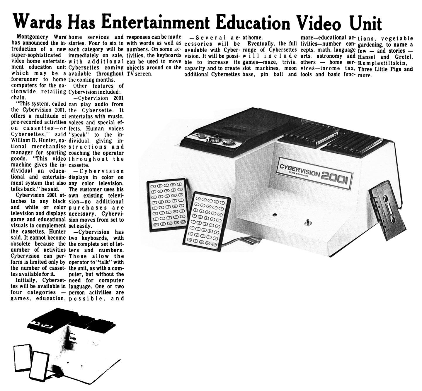
Wards Has Entertainment Education Video Unit
Montgomery Ward has announced the introduction of a new super-sophisticated video home entertainment education unit, which may be a forerunner to home computers the nationwide retail chain.
"This system, called the Cybervision 2001, offers a multitude of pre-recorded activities on cassettes—or Cybersettes," said William D. Hunter, national merchandise manager for sporting goods. "This video machine gives the individual an educational and entertainment system that also talks back," he said.
Cybervision 2001 attaches to any black and white or color television and displays game and educational visuals to complement the cassettes, Hunter said. It cannot become obsolete because the number of activities Cybervision can perform is limited only by the number of cassettes available for it.
Initially, Cybersettes will be available in four categories — games, education, home services and stories. Four to six in each category will be immediately on sale, with additional Cybersettes coming available throughout the coming months.
Other features of Cybervision included:
- Cybervision 2001 can play audio from the Cybersette. It entertains with music, voices and special effects. Human voices "speak" to the individual, giving instructions and coaching the operator throughout the cassette.
- Cybervision displays in color on any color television. The customer uses his own existing television—no additional purchases are necessary. Cybervision moves from set to set easily.
- Cybervision has two keyboards, with the complete set of letters and numbers. These allow the operator to "talk" with the unit, as with a computer, but without the need for computer language. One or two person activities are possible, and responses can be made with words as well as numbers. On some activities, the keyboards can be used to move objects around on the TV screen.
- Several accessories will be available with Cybervision. It will be possible to increase capacity and to create additional Cybersettes at home.
Eventually, the full range of Cybersettes will include:
- Games: Maze, trivia, slot machines, moon base, pinball and more.
- Educational Activities: Number concepts, math, language arts, astronomy and others.
- Home Services: Income tax, tools and basic functions, vegetable gardening, to name a few.
- Stories: Hansel and Gretal, Rumpelstiltskin, Three Little Pigs and more.
1978 Montgomery Ward Spring/Summer Catalog

Wards has what's new
"Let me introduce myself... I'm the Cybervision 2001 TV home computer system...and I've been programmed to talk. I can play games, teach math, or help with your tax return."
$399
A new generation of home computers is emerging, and now the family can enjoy the power of this extraordinary machine. Growing interest in the home computer market has encouraged Wards to develop the Cybervision 2001. Here's an extremely sophisticated computer that's easy to operate...at a remarkably low price. Simply hook it up to any black and white or color TV — anyone can operate it, no computer knowledge is required. Cassette tapes, or Cybersettes, direct the computer — the computer then teaches you how to use it, talks to you, prompts questions about the program you have chosen and helps you choose your own skill level. Wards is developing hundreds of these Cybersettes in many categories. See opposite page for a detailed description and complete listing of our 4 initial Cybersette series: Game, Education, Home and Story.
The Cybervision 2001 can use an unlimited number of Cybersettes...you will even be able to prepare your own Cybersette with a blank tape. Unit functions in full color with audio and visual effects. Data transfer (tape to screen) is faster than any home computer of its kind. Included are cassette recorder, storage rack that holds up to 12 Cybersettes, and 2 hand control key pads with full alphabet and numeral sequences. Also included are storage pouch for the key pads, power cable converter, antenna cable, antenna switch, instruction manual, and one introductory Cybersette with 8 programs: TV adjustments; Bed-time Story; Trivia; Sub-Chase; Biocycles (shown on screen above); Designer; Math Fun; Bulldozer. Cabinet is structural foam. For 1 or 2 people, with possibilities for group activities.
60 B 95090 — 14.5 x 11.5 x 5.25 in. high. Shipping weight 15 lbs... $399
TV set not included, see pages 869-873. See more electronic TV games on page 510.
Game Series: Play all the great arcade games like Moon Base (shown above), Starship, Bullfight and many, many more right in your own home. With Cybervision 2001, programming potential is unlimited. See our complete selection of games and their availability dates at right. More and more Cybersettes are being programmed every day...they'll be available soon.
Educational Series: Start an educational library of Cybersettes and help improve the quality of your child's school work. Levels range from preschool through college. Cybervision 2001 automatically adjusts learning pace from remedial to advanced. See our complete selection of educational Cybersettes and their availability dates at right. More programs coming soon.
Home Series: Cybervision 2001 really shows its endless versatility in this series. Geared for adults, it is a helpful aid in preparing income tax, balancing a checkbook, keeping a vegetable garden and countless other household activities. See our complete selection of home service Cybersettes and their availability dates at right. More home service programs to come.
Story Series: Great fun for the kids to watch and listen! Timeless fairy tales like Hansel and Gretel (shown above). Rumpelstiltskin or Beauty and the Beast are yours to enjoy at a moment's notice. Start a collection now of your all-time favorites. See our complete selection of stories and their availability dates at right. Watch for more stories being programmed every day.
* Join Wards Cybersette Club and receive advance notice on all new Cybersettes. Just mail the card included with the unit.
[List of Cybersettes from this catalog are included earlier on in my blog, under Cassette (Cybersette) Releases.]
Newspaper Advertisement #1 (November 1978)
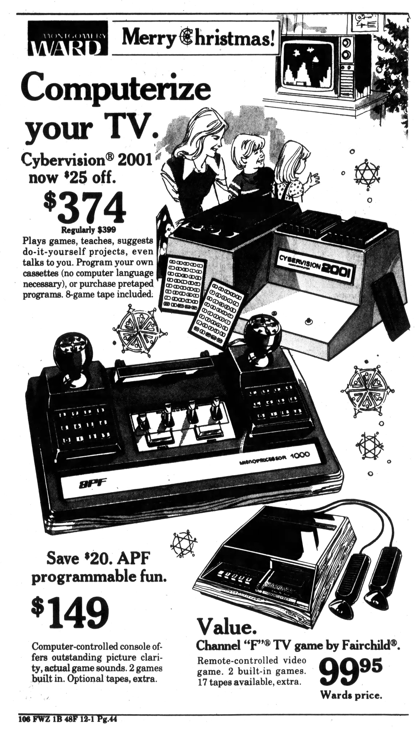
Computerize your TV. Cybervision 2001 now $25 off.. $74 - Regularly $399.
Plays games, teaches, suggests do-it-yourself projects, even talks to you. Program your own cassettes (no computer language necessary), or purchase pretaped programs. 8-game tape included.
Newspaper Advertisement #2 (December 1978)
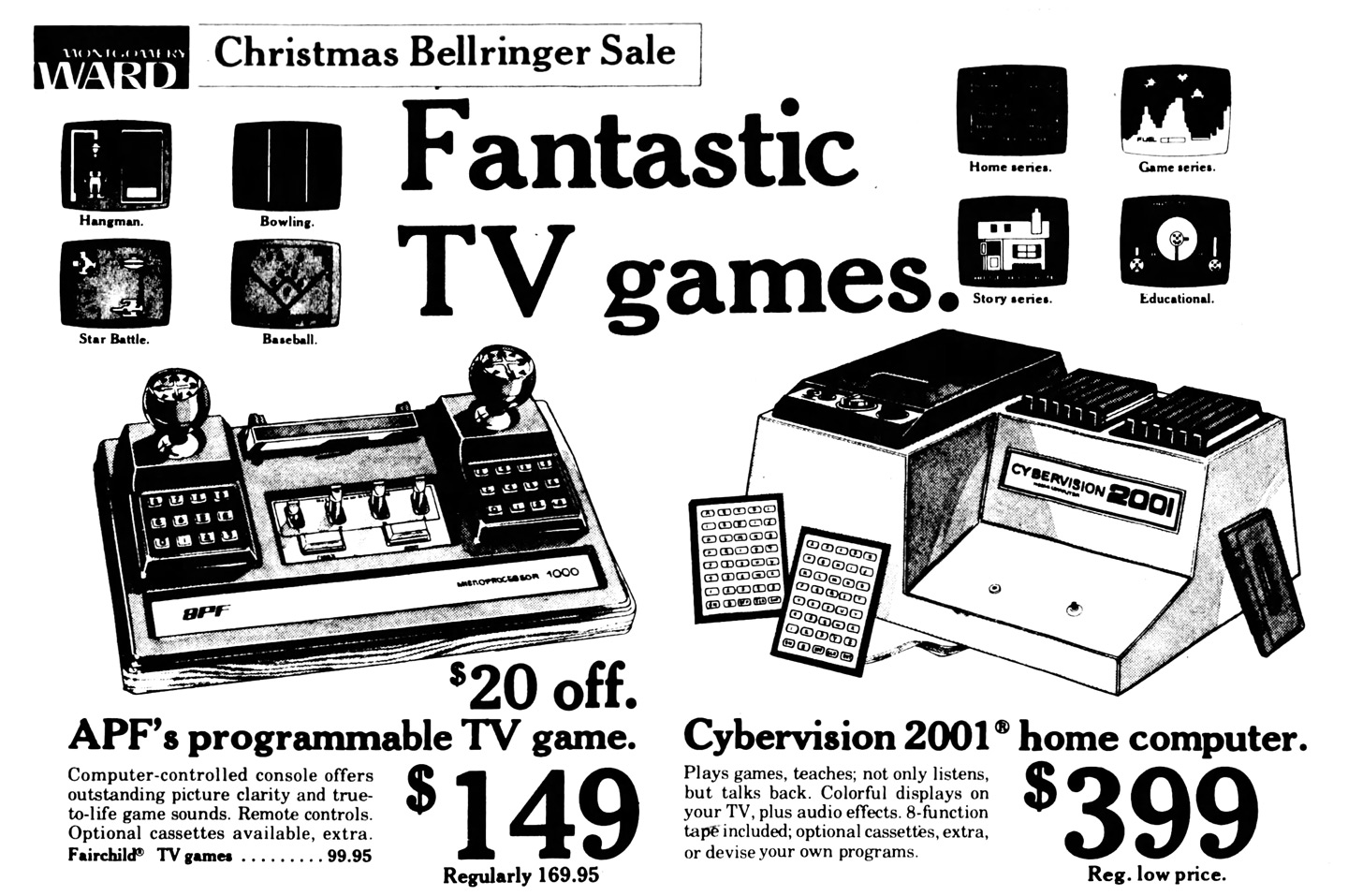
Fantastic TV Games. Cybervision 2001 home computer. $399 Reg. Low Price.
Plays games, teaches; not only listens, but talks back. Colorful displays on your TV, plus audio effects. 8-function tape included; optional cassettes, extra, or devise your own programs.
Creative Computing (September-October 1978)

CyberVision 2001. Console contains MPU, 4K RAM, single cassette deck and built-in speaker. Two alphanumeric touch sensitive keypads are included. The unit attaches to a color TV set. It runs Tiny BASIC but most of the pre-programmed cassettes are in machine code. Because of the relatively small built-in memory, programs use continuous overlays; i.e., keep the cassette running, but this introduces some neat possibilities with the separate audio track — storytelling, spelling and language drill and audio prompts in programs. This is the unit sold through the Montgomery Ward catalog.
- CyberVision 2001 uses stereo cassette tape with one track for programs and one for audio.
- CyberVision 2001 control has full alphabet and numerals on touch sensitive pad.
(See interview with John R. Powers III.)
Creative Computing (April 1979)

You haven't seen this one before. The Cybervision 2001, which was originally introduced in the Spring '78 Montgomery Ward catalog, has undergone a facelift. This is the Cybervision 4001, which will be available about the middle of this year. The collection of educational and graphics games available for the 2001 (and 4001) is impressive. The system uses dual 1802 microprocessors in a multiprocessing mode and some of the techniques they use are fascinating. Hopefully, we'll have a review of the system soon.
Broadrein Instruments, 1057 Checkrein Ave., Columbus, OH 43229
Creative Computing (August 1979)

CyberVision
The CyberVision system made by Broadrein Instruments has an impressive collection of Interactive children's stories available for it. The original CyberVision 2001 was only available through Montgomery Wards but we are promised that the new models will be available through other outlets as well.
Trademark Application
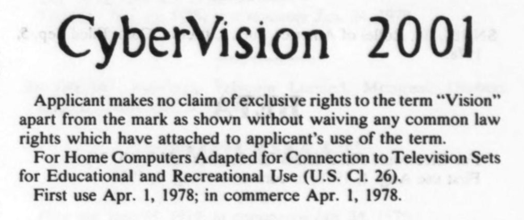
CyberVision 2001
Applicant makes no claim of exclusive rights to the term "Vision" apart from the mark shown without waiving any common law rights which have attached to applicant's use of the term.
For Home Computers Adapter for Connection to Television Sets for Educational and Recreational Use (U.S. Cl. 26).
First use Apr. 1, 1978; in commerce Apr. 1, 1978.
Serial Number: 73178912
Filing Date: July 20, 1978
Registration Number: 1137246
Registration Date: June 24, 1980
Applicant/Owner: CYBER VISION INC.
Mark Drawing Code: Drawing with Words in Stylized form
Cancelled: November 20, 1986
Cybervision Team: The Authorship Resource, Inc.

The engineering group behind Cybervision is fairly small. This is an incomplete list, but will be added to as I discover more. Much has been derived from interviews and articles including from Matt Powers, son of co-founder John Powers.
- Company: The Authorship Resource Inc. (ARI)
- Entity #: 495875
- Filing Type: Corporation For Profit
- Original Filing Date: April 1, 1977
- Location: Columbus Franklin Ohio
- Agent Resignation: January 7, 1982
- Company Cancellation: April 7, 1982
- John P. Powers III: Co-Founder (ANTIC Interview)
- "I was a software developer for the CyberVision 2001 from its inception to its demise. My business partner and I developed its operating system and, with the rest of our software development team, all of the nearly 30 applications for the CyberVision. We have CyberVisions in the attic and, the last time we checked, they still worked. We also have copies of all the applications that were developed. Myself and Ken Balthaser, one of the original CyberVision software development team members, reunited 35 years later (in 2012) to produce a game for the iPhone and iPad. There more information about our background and the game at the game's web site - www.startruxgame.com.Life comes full circle -- Two guys that worked at the leading edge of home computers in 1978 are reunited 35 years later to work together at the leading edge of mobile computers." (January 7, 2014)
- Joe Miller: Co-Founder (In Memoriam) (Detailed Biography)
- "I was John's business partner and co-founder of the company that developed the CyberVision 2001 (3001, and 4001) and I can tell you that the product was released and sold nationally by Montgomery Ward in 1978. We had an order from Ward's for 10,000 units of the initial product configuration (pictured in the Ditlea book) that we fulfilled, and a new form-factor (model 3001) was released on a second round of orders from Wards. We also developed a prototype of a much sleeker looking 4001 model, which included an extended adaptation of Ron Cenker's floating point BASIC in ROM. That model was never manufactured in quantity. I won't get into it in this reply, but it turns out there is a connection between the CyberVision lineage and the Astrocade/Bally system. As John mentioned, we have several working versions of each of the models produced (including the 4001 prototype) and the entire software library (over 40 titles) for this RCA 1802-based home computer." (March 17, 2014)
- Brenda Laurel: Designer, Programmer and Manager (July 1997 Interview) (January 2017 Interview) (Wikipedia)
- "The CyberVision computer only had 2K of usable RAM. [Laughs.]. We were loading code from cassette tape, and, luckily, that meant we were able to speak character’s lines. We would do an audio recording within little interrupts that would cue actions to happen on the screen. That was the bonus, but the downside was you could only squirt 2K in there. You had to have basically a converging node, because the player couldn’t make a choice that would really influence the action. We didn’t have enough memory to store those choices, even if we would have had an elaborate branching structure. You could imagine it was really frustrating. Just asking the question of, “What could this be? What is this thing called interaction?” was sort of the formative moment of my career." (January 10, 2017)
- Ken (Eiko) Balthaser (ANTIC Interview)
- "We developed all of the software. In those days there were no tools, nobody knew. This is a brand new industry. Apple, about that time, I think they were selling their Apple in kit form. Which you could buy, like a Heathkit, to build an Apple computer. And you know, we were just inventing things along the way. We had to, we had to make our own tools. There were no tools to create art, to create sound or anything. We didn't even have a display to do our programming. I mean, we programmed off of, what were then used DECwriters. They were these upright printers with a keyboard and you entered code right there and printed it out on paper. There were no monitors or anything like that. The operating system, the little computer that we used for development, didn't even have an operating system that would manage your files. We had to do all of that by hand. You talk about primitive!" (April 9, 2015)
- Janey Powers (Computers as Theatre)
- "I became a software designer and programmer, working primarily on interactive fairy tales and educational programs for children. The company was called CyberVision, and the machine was a lowly 1802 processor with a four-color, low resolution display and an alphanumeric keypad. The CyberVision computer was cassette-loaded with 2K of RAM, and it had the capacity to synchronize taped audio with animation on the screen. My first "feature" was an interactive, animated version of Goldilocks. Later, I created the first lip-synching on a microcomputer for a game of Hangman in which the evil executioner delivered menacing lines in a Transylvanian accent (all this with only sixteen lip positions). I immediately became immersed in translating my knowledge of drama and theatre to the task at hand because the two media were so obviously alike. When CyberVision folded to its competition (an upstart company called Atari), I asked my boss to help me think about what kind of job to look for next. He said, "Why don't you go work for a bank? They need people to help design automated teller machines." "I don't know anything about that," I cried. "Of course you do," he replied. "That's human factors." In response to my blank look, he elaborated: "That's making computer things easy for people to use." (September 27, 2013)
- John McMullin and Jim McConnell - Hardware engineers
- Thomas G. Adams - Registered Agent of The Authorship Resource, Inc.
Interview with Ken Balthaser (April 9, 2015)
The podcast ANTIC: The Atari 8-Bit Podcast conducted an interview with Ken Balthaser in 2015, hosted by Kevin Savetz. Below are the Cybervision-related transcribed excerpts from it.
Q: I know that you were manager of software development at Atari, but before we get there I see that you were a designer and programmer at The Authorship Resource, which was making software for the Cybervision 2001 computer.
BALTHASER: Yeah, that's right. Mm hmm.
Q: I know a lot about old computers and I don't think I've ever heard of this one. So I was hoping we could take just a couple minutes, you could tell me about that position and what you did there.
BALTHASER: It's a little known computer. A little 8-bit microcomputer that was developed back in Columbus, Ohio. It was sold by Montgomery Ward. In those days, Ward was a big retailer like Sears, I don't know if you remember or not. Anyway, they contracted to have this little home computer built. They thought computers were the next big coming thing.They had enormous success selling Pong games and things like that.
So yeah, I was part of a very small crew that, in 1978, began working on creating software. We created all of the software including the operating system for that little system. It was sold by Montgomery Ward, it was an 8-bit computer. It had some unique features about it. We always thought it was actually the very first home computer because it's what it was designed for, to be used in the home and mainly for educational purposes.
But it used the RCA 1802 microprocessor. And this was a CMOS processor that was actually used by NASA in the space program. But being CMOS it was very little power requirements. So it used the RCA 1802. It was, compared to this day, obviously very primitive machine. It had four colors. It hooked up to a standard television set.
And it used, the most unique feature about the system was it used a standard audio cassette to do two things. One, is to load data into memory. And the other was to use, it used a stereo system so one track was used to load data, the other track was used to load soundtracks. So we could actually do voice and we actually went into the studio. That's why I was hired initially, because of my background in broadcasting. I was hired to create the audio tracks for the computer.
And so, now I'd go into the studio and bring talent in and we'd do kind of a variety of software products. From entertainment with its, you know, simple games like Sub Chase and things like that. We did adult instructional things like home vegetable gardening and things like that. We had a little checkbook balancer program and bedtime stories for children, which were a lot of fun to do. And so forth. The neat thing about that was the system only had 2K of memory—2K of display memory, and 2K of useful programming memory. It's hard to imagine a system like that, today.
Q: Yeah, that's crazy small. Even by that time. That seems limited.
BALTHASER: Yeah. So in order to get around the limited memory, we used the cassette for storage. What this meant was we could load data on the fly, while there was audio going on. We'd load data in the background. So essentially we could have very large programs running and the user wasn't aware of it, that data would be loading off of the other channel. So that was truly a multimedia machine.
We developed all of the software. In those days there were no tools, nobody knew. This is a brand new industry. Apple, about that time, I think they were selling their Apple in kit form. Which you could buy, like a Heathkit, to build an Apple computer. And you know, we were just inventing things along the way. We had to, we had to make our own tools. There were no tools to create art, to create sound or anything. We didn't even have a display to do our programming. I mean, we programmed off of, what were then used DECwriters. They were these upright printers with a keyboard and you entered code right there and printed it out on paper. There were no monitors or anything like that. The operating system, the little computer that we used for development, didn't even have an operating system that would manage your files. We had to do all of that by hand. You talk about primitive!
The neat thing was, we did develop ways to get non-technical, non-computer people to actually create programs for this system. They were writing binary code basically and they didn't even know it. We just had instructions on, you know, we developed all kinds of tools, layout tools for graphics and animation and so forth. So, we just invented things on the fly. And we developed, as is usual in software, we way overpromised Montgomery Ward what we could do. But we did manage to get, I think, something like a dozen of fifteen programs out in a fairly short time.
We were under pressure because they featured us on the front two-pages of their massive catalog that they sent out to their customers, so we were under enormous pressure to get that done. So anyway, Montgomery Ward sold it and distributed it. The only thing was, everything was so new they had nowhere to sell it. They didn't have an electronics department at that time at Montgomery Ward. So they sold this system in the sporting goods department of all things. So, needless to say, it wasn't a spectacular success.
I think their initial order was 50,000 units, and we delivered those units to them but shortly after that the company ran low on money, ran out of money eventually and went south. It was just one of those eras of a lot of companies out there trying to do something and maybe we were at the wrong place at the wrong time. Columbus Ohio was not the heart of technical creativity in those days, or venture capital or anything like that. Maybe if we had been out in California here, in the Silicon Valley, it would had been different. But anyway, the small group of us there, all came out west after the Authorship Resource was eventually absorbed by Cybervision, the company. When Cybervision went out, a group of us came out to California to work, and to work for Atari specifically.
Q: Now did you come out with the intention of getting hired by Atari, or did all of you have secured jobs before you came out to California?
BALTHASER: No, no. It wasn't in one mass exodus. It was, you know, everybody was stunned when things went south and the first person to come out—the two founders of Authorship Resource were John Powers and Joe Miller. John Powers flew out first to interview, just to come out to Silicon Valley to interview for a job. He had interviewed for some data processing company, I think in Florida and flew down there, and was almost ready to take a job down there.
Then he flew to California and had an interview at Atari when they were breaking off their Atari video game system and creating the personal computer system. So they had developed the Atari 400 and 800. And they needed a separate division and just so happened John's timing was perfect, they hired him to be director of software development. And from there then, John hired me, Brenda Laurel, Joe Miller and Jeff Schwamberger. So there were John, Joe, Jeff, Brenda, me—five of us that came out and worked for Atari.
Q: So sort of a lot of the crew from Authorship Resource picked up and went from Ohio to California.
BALTHASER: Yeah. We were basically the crew there doing all the software. The hardware engineer that had been at the hardware system, he came out to interview but he just couldn't make the transition so he opted to stay back in Columbus and his technicians stayed there. But to us five that were the heart of the software crew came out here and worked for the Atari personal computer system [starting in spring of 1980].
External Resources for Further Reading
- Cosmac Elf - CyberVision Gallery - Overview with contributed materials from John Powers, co-founder of Authorship Resource Inc. (ARI) which developed the OS and software for the CyberVision 2001, 3001 and prototype 4001.
- A Brief History of Video Game Development - Overview of 1970s game development including antidotes about Cybervision from a son of a developer (Matt Powers, February 24, 2014)
- The History of a Forgotten Computer: Part 1 - Detailed story of how the CyberVision came to be with interviews by those involved. (Matt Powers, April 25, 2014)
- The History of a Forgotten Computer: Part 2 - Continuation of the article above, with a detailed perspective offered by Ken Balthaser (ARI). (Matt Powers, May 4, 2014)
- Simple Guide to Home Computers (Extract) - Excerpts from a book that discusses the CyberVision, Bally and other systems from the time.
- Home Computer Designations of the Late 1970s: A Feature Article - An article with comment replies by various members who worked on Cybervision including Joe Miller and John Powers. (Bill Loguidice, August 11, 2010)
- John Powers
- Joe Miller :
- Do you recall the least popular microprocessor of all? - Rundown of the RCA 1802 CPU in a larger scope, which also includes Cybervision as one of the few home computers that utilized it.
- Antic Atari 8-Bit Podcast: Interview with Ken Balthaser - April 9, 2015
A Personal Call from Co-Founder John Powers
On February 8, 2023, I had a pleasant phone conversation with John Powers, co-founder of Authorship Resource Inc. He was forwarded my current progress and enthusiasm over the Cybervision from his son Matt, who had made the excellent two part series about the Cybervision origins back in 2014. It was great to speak personally with the man who, as he explained over the call, pulled a 24+ hour binge typing in hex code into a DECwriter to create the eventual operating system that the Cybervision required. John's company was instrumental in all of the software produced for the system and the core five members of the software team eventually landed gigs at Atari and beyond.
During the call, John recounted what a big deal it was at the time to be featured so prominently in the Montgomery Ward catalog — the opening two pages of the 2000+ page mammoth of consumer goods. John remains active in the software development field, having created both commercial and personal applications on mobile platforms including on-going efforts with iOS (and a very cool throwback to the original Cybervision SubChase, which he graciously allowed me to test on my iPhone). There may be more to come on this front with continued correspondence, stay tuned.
Blog Update Notes
2023/03/22: Added progress update on ROM repair and disassembly (very close now thanks to 1802 experts, to the point where emulation of this system is now also in beta and I can run the repaired ROM from a physical device). Also added note about redoing the fragile controller wiring to the logic board in a more removable manner. I am also working on a more dedicated webpage to house all CyberVision information in a more logical fashion, it will be available at https://cybervision.mattpilz.com/.
2023/03/02: Added a section about additional problems I'm currently experiencing on the repair effort, as well as a section on the ROM itself.
2023/02/18: Added a blurb recounting my recent phone conversation with co-founder of Authorship Resource Inc. and developer of Cybervision OS and software, John Powers. Also added a section about the audio amplifier and some additional cassette deck details.
2023/02/13: Added sections about the staff and founders of The Authorship Resource, Inc., transcribed some interviews and content, added more articles and excerpts that Cybervision was mentioned in.
2023/02/12: Added section on published articles including images and transcriptions. Expanded Cassette (Cybersette) Releases section to include the more than 40 titles listed between catalog and advertising. Added section with highish resolution photos of the front and back of the main logic board.
2023/02/11: Fixed controller issues after pinpointing a bad transistor. Added some more info about the controller layout, and another section about the audio data input.
2023/02/08: Performed a detailed audit of the 89 integrated circuits on the board and added a table with details of each. Also added a section about TI's SN76430N that is used as the video generation.
2023/02/06: Added new section titled "More on Cassette Reverse Engineering" including my current understanding of the cassette load lifecycle. Also added a section called "Controller Problems and Analysis" where I begin to detail my findings about defective controller input.
2023/02/05: Added new section stub for cassette documentation and discoveries.
2023/01/26: Added new section stub about voltage regulators.
Pingback: A Dedicated CyberVision Website! – CyberVision 2001 Information Portal
Nice article on the Cybervision Matt. I was an engineer at the company that built the hardware. The Cybervision was a fun product to work on. The production units had a plastic case, not wood so I wonder if you don't have a prototype.
Great to hear from you, Mike! I know quite a bit about the software side of CyberVision's development at this point via ARI contacts, but not much on the hardware front. I forgot to update my blog since my original observations on the physical unit, but it is indeed structured foam / plastic and matches the look of the one seen in the instruction manual so I believe it was the ordinary consumer version. I noticed that the photos used in Montgomery Ward and other advertisements used a different looking case and cassette player, so those seemed to be earlier builds. I have seen "Broadrein Instruments" noted as the contact for CyberVision in some materials, but haven't found much about that company and its relation to ARI or CyberVision. I know it was also manufactured via Chem-Con / CyberVision Inc. My hardware repair effort continues going well, but has been tricky without schematics or service manuals! I'm currently struggling to repair the cassette side of the system, to figure out the proper connections to power and cut control to the cassette motor based on the CPU/ROM data.
I have slowly been writing up a full Wikipedia article about CyberVision for greater discovery of this unique system. The draft version if it can be seen here: https://en.wikipedia.org/wiki/Draft:CyberVision_2001 - I am going to add additional images and some materials. I also am working on a more comprehensive knowledge base about the system at https://cybervision.mattpilz.com/ where I am hoping to also house interview transcripts and a lot of data in a friendlier format than this single blog posting.
If you ever want to touch base or offer any more insight into the hardware side of CyberVision you can also email me at info@matthewpilz.com. Thanks again for your comments and contributions to this fantastic system.
After watching the four or five CyberVision videos, in one intense reading session, I completely read "Retro Fix: Montgomery Ward CyberVision 2001" and the draft Wikipedia entry for the CyberVision 2001. I also read some of the "Further Reading" material. The Wikipedia draft is certainly ready to publish now. The list of "CyberVision 2001 Software Titles" will probably be removed from it, even though I think this list should be included.
Reading this article reminded me of printing out an early FAQ on the "Emerson Arcadia 2001" game console in 2001. (Including the full name of the CyberVision and the Arcadia console, plus the year I read the FAQ, that's three uses of that magical, futuristic, four-digit number!) At the time, 22 years ago, there was hardly anything written about the Arcadia 2001, an oddball videogame console which was thought to be unique, but later "discovered" to be licensed from overseas. Now it is easy to find out information about the Arcadia 2001. I hope that this article that covers the CyberVision 2001 finds fertile ground with others who help to dig deeper into the history of this fascinating computer.
Nice work, Matt!