


![]() As I've mentioned before, one of my favorite pastimes is vintage computing. I take particular interest in early connect-to-TV 8 bit microcomputers (including the short-lived Mattel Aquarius, for which I recently developed an extremely thorough, free modern online visual designer to assist fellow Aquarius artists and developers).
As I've mentioned before, one of my favorite pastimes is vintage computing. I take particular interest in early connect-to-TV 8 bit microcomputers (including the short-lived Mattel Aquarius, for which I recently developed an extremely thorough, free modern online visual designer to assist fellow Aquarius artists and developers).
And while I'm mostly a software guy, the aging nature of these vintage electronics leads to inevitable hardware faults and necessary maintenance, therefore it is still vital to be skillful on the hardware side as well. I recently wrapped up the most strenuous restoration project to date — an original TRS-80 Model I computer from 1977 with all the bells and whistles from that era. I don't usually document or write about my repair projects or 8-bit endeavors since I do it purely for the fun of it and personal enjoyment, but this was such a long and convoluted journey of highs and lows that I figured I should write a blog while aspects of it are still fresh in my mind. There are a lot of resources for TRS-80 computers out there already, but perhaps my shared experience will be of value or help to others trying to diagnose their own sets. If you have any questions, please feel free to ask in the comments.
This guide is not meant to be a deep dive of my own repair efforts, but rather a general plan of attack to troubleshoot any TRS-80, with many principles carrying over to other platforms as well. My endeavor of troubleshooting lasted more than 7 months of on-and-off attempts to fix a huge mix of problems that I hope few others have to deal with to such exhaustion. If this guide can help even one person in the future save the struggles I faced myself, bravo!
A Quick Jog Down TRS-80 Memory Lane
In 1977, Tandy (via Radio Shack) released its first TRS-80 home computer. For an initial advertised cost of "$600 to $15,000 (Kits and Assembled)" this was one of the major players in the early microcomputer boom, with Commodore and Apple making up the trifecta. This was an all-inclusive PC/Keyboard combination that hooked to a modified RCA consumer television set and allowed simple data transfer via cassette audio. The guts of the system were powered by a Z80 processor clocked to 1.774 MHz, with 80 integrated circuits cooperating to bring the system to life.
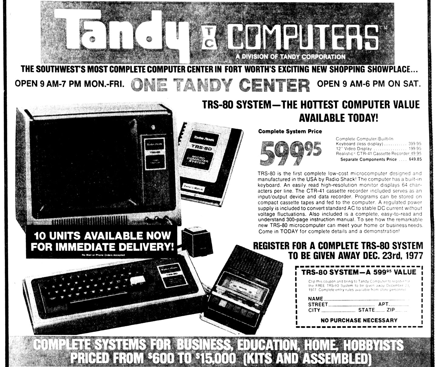
TRS-80 is the first complete low-cost microcomputer designed and manufactured in the USA by Radio Shack. The computer has a built-in keyboard. An easily read high-resolution monitor displays 64 characters per line. The CTR-41 cassette recorder included serves as an input/output device and data recorder. Programs can be stored on compact cassette tapes and fed to the computer. A regulated power supply is included to convert standard AC to stable DC current without voltage fluctuations. Also included is a complete, easy-to-read and understand 300-page instruction manual. To see how the remarkable new TRS-80 microcomputer can meet your home or business needs, come in TODAY for complete details and a demonstration. -Radio Shack 1977
The initial offering included 4K of 4116 RAM (across 8 memory sockets in the system) on a stripped down version of BASIC, upgradable to 16K. Although lowercase was technically available in the character set, it lacked a proper video RAM bit to support it without modifications. The original incarnation also lacked a numeric keypad, which could be purchased and installed separately, as was the case with the one I restored. Eventually they switched to the much more capable Microsoft BASIC as "Level II" that existing users could upgrade to for $159.95, as well as offered a variety of out-of-the-box configurations including 16K models, built-in lowercase support and more. In September 1978 they also introduced the TRS-80 Expansion Interface for power users for $399.95. The EI required Level II BASIC and supported an additional 32K of RAM, connections for up to four daisy-chained single density floppy drives, dual cassette decks, a real-time clock, printers and other custom expansions including RS232 interfacing. It was the missing link that turned the TRS-80 into a truly versatile powerhouse.
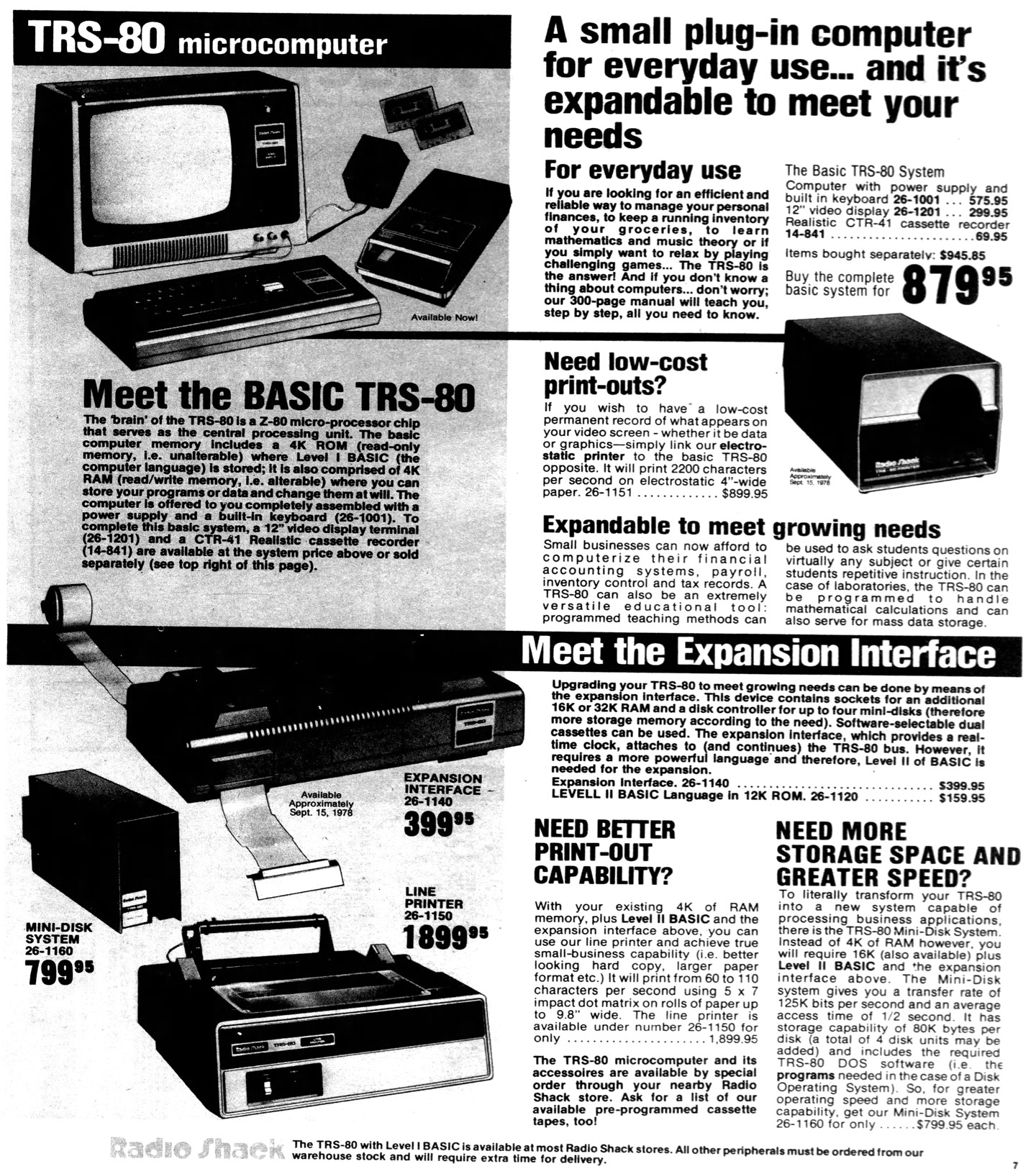
Upgrading your TRS-80 to meet growing needs can be done by means of the expansion interface. This device contains sockets for an additional 16K or 32K RAM and a disk controller for up to four mini-disks (therefore more storage memory according to the need). Software-selectable dual cassettes can be used. The expansion interface, which provides a real-time clock, attaches to (and continues) the TRS-80 bus. However, it requires a more powerful language and therefore, Level II of BASIC is needed for the expansion. -Radio Shack (1978)
The system, later amended in name to TRS-80 Model I, proved successful enough to spawn a series of follow-up computers including the Model II (for business and academic uses), Model III, Model 4/4D/4P and some others, with more than 2.4 million sold across the various models. The same branding was used for the Color Computer series of the 1980s, although the underlying hardware was vastly different on those sets. Despite the system having only monochromatic display (black and white), a fixed character visual pipeline, no integrated audio and constrained technical specs, it was captivating. The simplicity of saving and reading data from ordinary cassette tapes combined with the expansion capabilities of floppy disks and other peripherals proved pivotal to the advent of indie software development, paving the way for thousands of future developers and computer engineers.
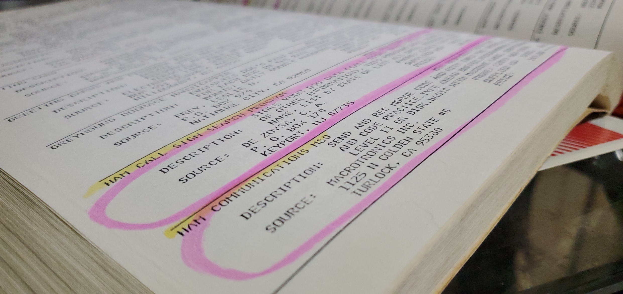
From a box of TRS-80 books and documentation I'd acquired over the years, I discovered Volume III of Radio Shack's "TRS-80 Applications Software Sourcebook." This was a regularly updated catalog spanning hundreds of pages of software. It still has the original Radio Shack price tag affixed at $2.95. The listings include more than 2,300 software applications for the original TRS-80 line of computers. Flipping through the pages, I saw a variety of applications highlighted and circled, which I like to envision was similar to a child thumbing through a toy catalog and circling hopeful gifts. The original owner of this catalog from decades past took a liking to programs relating to Ham Radio and Morse Code.
Now 50% More Program Listings! Over 2,300 In All! A listing of applications software for the TRS-80, including author, program, description, types of media available, minimum equipment required, price, and ordering information. Listings for Games, Business Applications, and Home Use. -Radio Shack Catalog Number 26-2114
From a Bunch of Broken Pieces and Fried ICs...
My journey into TRS-80 repair began about seven months prior to this post. I had acquired some odds and ends including an original TRS-80 monitor (which is really just a shelled out, painted and rebranded consumer 13" RCA television for cost-reduction reasons). Unfortunately, the actual TRS-80 components I likewise received were shattered into lowly states of despair.
The plastic moldings used for the TRS-80 computer and expansion interface, like many others, have grown brittle over time. Even shipments from the same state can end up catastrophic in transit unless they are very carefully packaged. At another point I received more TRS-80 components that also had been devastated in transit.
As a sporadic collector of vintage sets I ultimately wound up with several TRS-80 components in dire condition. None of them worked. Most were physically damaged, but I did also get a hold of a more pristine casing from another parts machine.
Packaging Pro Tip: Sellers who do not ordinarily deal with vintage electronics may not understand the intricacies of safe shipping. In the instances where I've received busted products, it is often because they ship all components including heavy power adapters or other accessories loose in one box; the internal weight is enough to bust up the plastic and more. As a courtesy in light of numerous failings, I now try to offer some words of wisdom to would-be sellers before they ship any items that I know are fragile. Most people appreciate this advise upfront rather than dealing with the headache of returns and refunds in the event of disaster. Although I vary my wording based on the context, below is a paraphrased example.
To ensure safe transit in the mail, please wrap each main component (e.g., computer, floppy drive, expansion interface) in bubble wrap and place each in its own snug box, padded by an inch or two of packing peanuts. Then place each of these individually sealed boxes into one main box for shipment, again padding between the individual boxes with foam, peanuts or bubble wrap. Any adapters and cabling that is detachable should be detached, and all of these cabling peripherals can be wrapped in their own box alongside the others. The goal is to reduce both internal and external movement and potential for damaging impact.
With each peripheral protected both internally and externally, it should more readily survive even rough handling in the mail. The individual boxes should be padded inside the main box in such a way to not allow much shifting or movement when transit, so use appropriate sized boxes to leave an inch or two of peanut cushioning on all sides but not too big that any of the parts will tumble excessively into each other.
For monitors and TVs, consider cutting down a foam noodle and running it along the front bezel then encasing the unit in bubble wrap. Pack the CRT face-down in the box to mitigate weight against its casing. Put "FRAGILE / HANDLE WITH CARE / CONTAINS GLASS" and "THIS SIDE UP" labels clearly on the box. Insurance is a must and taking these cautionary measures will also help prove that the packaging was adequate in the event of serious damage caused by a mail carrier.
If this added attention to packaging requires extra cost for materials, please let me know and I'd be happy to cover the difference to ensure safe transit.
The damage of these sets exceeded just cosmetics. There were broken sockets, torn out bodge wires of unknown origin, partially removed toggle switches and other modifications. Since the exterior of every TRS-80 Model I is identical (or can easily be made so using various face places, such as a cut-out or cover for the optional number pad) my plan of attack to get a working one would be to start with the most vanilla base possible and eventually transpose everything into an unbusted case. Using the rest of the components and broken shell pieces as parts and spares, and potentially even gluing back the cases to some usable state.
Troubleshooting Prerequisites: Before Powering Up
It is always worthwhile to do a thorough visual inspection of vintage systems before powering them up. With the TRS-80 series or most others, this involves opening up the case and checking for any leaked or dislodged capacitors, bent sockets, broken wires or other abnormalities. At this point it is also worthwhile to do a basic clean-up to remove any obvious dust or grime. Compressed air and paper toweling will suffice. You should also consider carefully removing and reseating any socketed chips in case they have become ajar. While they are out, the sockets can be cleaned with Deoxit D100 or other electronic contact cleaner. and the legs of the IC chips can be assessed to ensure no corrosion and cleaned with Isopropyl Alcohol 91% higher. If you have an ESR meter such as the MESR-100 and there are some large electrolytic capacitors, you can check those for anything heavily out of whack while you have the board exposed.
Electrolytics from the 1950s-1980s are now largely exceeding their stability and in time will benefit from replacement. Paper, cardboard and wax electrolytics should always be replaced since these tend to have the worst leakage and other problems. My mindset is that the effort to test old electrolytic capacitors generally exceeds simply replacing them anyway to ensure years of maintenance-free continuance, since to do a proper test you have to remove them from circuit anyway and have some fairly specialized tools. The two major electrolytics for the TRS-80 are C8 (Axial 2200uF @ 35V) and C9 (Axial 10000uF @ 16V), part of the power grid. These same values exist in the Expansion Interface as well. After checking ESR readings I determined one was 3x over the max cut-off, and one was of the cardboard style that may had been replaced decades ago, so I replaced both with fresh electrolytics.
 Battery Warning: If you are dealing with computer systems or other electronics, especially from the 1980s-90s, many of them will also have an internal battery for clock keeping or system settings preservation. The original line of Macintosh computers (and the IIGS) as well as 286-486 desktop computers are notorious for leaking batteries affixed to the motherboard. If not removed promptly, and depending on storage conditions and other factors, the batteries can spit voluminous acid out and eat through the entire motherboard, even corroding the frame itself. I've experienced this on numerous machines after acquiring them, including several old model Macs and Packard Bells. I recommend removing any batteries that may be in these old devices as soon as you are able to even if they look stable, and replacing them with simple battery packs of equivalent voltage — preferably place the external packs somewhere in the computer where leakage won't damage any of the circuitry. I wrote a quick guide on doing that, here, but you can also find readily available premade packs on eBay. The TRS-80 has no batteries within it, so we are good there.
Schematics and Technical Reference Guides
To do any deep troubleshooting or even cursory review of voltages and so on, we really need to get a hold of the schematics and component lists. Thankfully there has been a great effort by TRS-80 users to archive publications and make them available online. The must-have sources for troubleshooting these components include:
- TRS-80 Micro Computer Technical Reference Handbook 2nd (1982) (Radio Shack) - An extremely readable official technical guide that includes common checkpoints, schematics, part lists and theories of operation.
- Sams ComputerFacts - Model I (1985) (Howard Sams) - The defacto for schematics and servicing, includes details about TRS-80 computer, expansion interface and monitor.
- Sams Computerfacts - Disk Drive (1985) (Howard Sams) - For floppy drive troubleshooting. Even third party floppy drives are often very similar to what's covered in this documentation.
- Tandon TM100 Floppy Drive (1982) (Tandon) - One of the popular drive models back in the day.
- Tandon TM-50 Service Manual (1983) (Tandon) - Another popular style drive.
There are actually many very valuable reference books and guides published for the TRS-80. Even the basic user guides can be helpful in understanding their operations and how things should work.
The TRS-80 Archives at ClassicCmp contain a massive collection of manual-related materials for download, and is the source I link to for the documents above. Even when your TRS-80 is up and running, this is an incredible source to find books about programming, newsletters, magazines and much more. ClassicCmp actually has archives overing many topics, and is easy to go down rabbit holes of discovery. You can also find more than 770 TRS-80 related manuals uploaded to the Archive.org TRS-80 Manuals collection, although this mixes many models so you may want to refine your search.
Voltage Checks: Power Supply
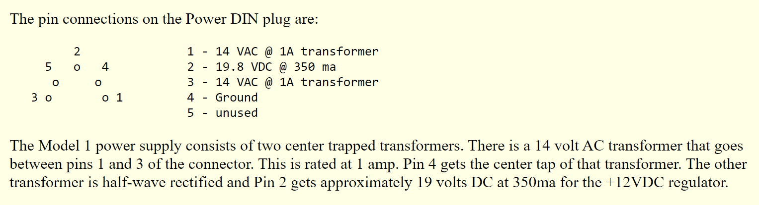
Before connecting the TRS-80 to an outlet, you should also verify that the voltage of the power supply is in spec. I find the power supplies to be generally stable even all these years later. You can compare the voltage using a multimeter by checking the corresponding pins, descriptions of which are provided on the back of the charger and in the schematics. Some helpful pin-out details for all ports and connectors can also be found on this old TRS-80 Internals page.
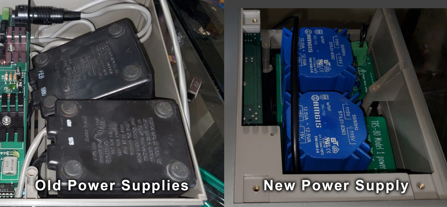
There is also a modern power supply alternative that not only comes with the comfort of knowing all the components are new, but can conveniently power both the expansion interface and TRS-80 computer with a single plug instead of needing two power bricks. Ian Mavric is the man when it comes to acquiring rare original components and new builds for the TRS-80 line (his website is here), including the heavy duty modern power supply kit. Although Ian is from Australia, I ordered quite a few different items from him this year and the shipments are always prompt and accurate. If you are state-side, you may also wish to reach out to some of the members of the TRS-80 Facebook Group who are often happy to help. My modern power supply, prebuilt with transformers, was acquired from Jay Newirth for a very reasonable price and turnaround time. The modified power supply (Circuit design by Dean Bear; PCB Layout by David Mutimer) fits right into the expansion interface case just as two old power supplies would, and the cables can be routed out the back as usual but you only need one outlet. The new PSU also has a lovely bright green glow that shines subtly through the EI vents, which can serve to remind you that it is powered up.

Voltage Checks: Internal Voltage
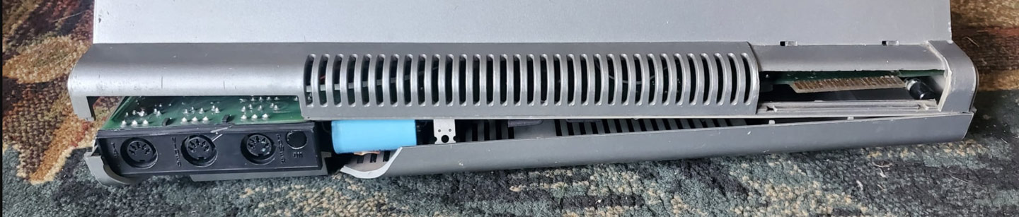
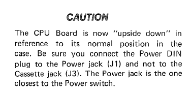
Now that all the housekeeping is out of the way, it is time to connect the machine and check the internal voltage. First ensure that the power button on the back of the TRS-80 is switched off (outward). Then connect the power adapter to the POWER 5-pin socket on the computer, but please heed the warning below before you do this.
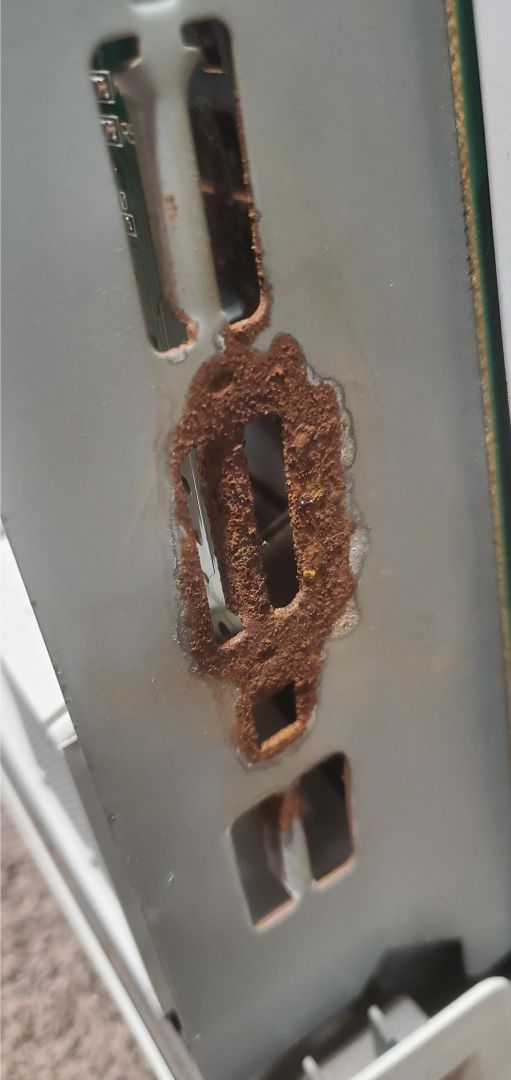
 MAJOR WARNING - CONNECTOR PORTS: Tandy decided to design the TRS-80 Model I generically whereby all three of the vital connectors (Power Supply, Video, Cassette) utilize a common DIN-5 plug. The risk potential of accidentally plugging the power connector into either of the other two ports is very high. In fact, one of the fried sets I received specifically noted that it was getting no power after accidentally plugging in the power cord to the video port, among other problems. This is made even more mistake-prone considering the original devices all used the same gray cable and black tip! Consider marking the ports and plugs to avoid unnecessary damage. The modern PSU has an all black power cord so at least that helps distinguish it. You really don't want high voltage going into pins and traces that it shouldn't.
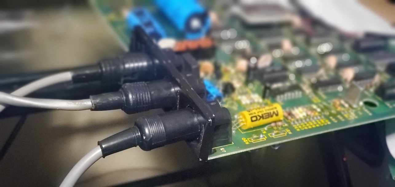
Choose Wisely: All three connectors have the same end plug and color scheme. Consider marking them in some way to prevent plugging the hot voltage into the video or cassette ports.
The circuitry of the TRS-80 relies on 12V, 5V and -5V to power all of the components. When I first powered it on, I realized there was no power getting to the keyboard, no LED, no sign of life. As such the first approach is to make sure all three of these voltages exist and are within spec. This can be done in many different ways, but two simple approaches are provided between the TRS Technical Reference Handbook (2nd Ed.) and the Sams ComputerFacts file. The method I use most often is to clamp a lead onto the negative side of the large 10k electrolytic (C9), and then take the positive probe and touch the topmost side of R18 to measure 12V. If it is off, adjust variable resistor R10 (or R7 depending on board revision) until it is accurate; you should use a non-conductive screwdriver or similar adjustment tool for maximum accuracy while adjusting. After the 12V is accurate (11.4V to 12.6V is considered normal), then you can measure the 5V using the left side of R4. Again any inaccuracies should be adjusted via R5 (or R8 depending on board revision) until it falls within 4.75V to 5.25V.

The 12V and 5V checks and adjustments, as detailed in Sams ComputerFacts TRS-80 (LEFT) and Radio Shack TRS-80 Technical Reference Handbook (RIGHT)
There is a great summary about the system power chain and operations from pages 52-54 in the TRS Technical Reference Handbook (2nd Ed.), too. One of the initial obvious problems with my set was that I was not getting any 5V reading. Before further troubleshooting this, I realized the original vertical variable resistors to adjust voltage were overly sensitive and sporadic — a common issue due to corrosion or adverse elements. While Deoxit F5 can do wonders for potentiometers and variable resistors and I have used it successfully on everything from volume knobs to Pong controllers, in this case I decided I'd rather replace the 1K resistors outright. Another problem that seemed to be happening was that just by working on the board, the outer-facing adjustment controls were getting nudged and screwing up the voltage unsuspectingly, so I'd have to regularly double check it. The new replacements were much more stable and wouldn't be accidentally altered.

I replaced the original large electrolytic capacitors and also swapped out the flawed voltage variable resistors to flat horizontal style that will be less prone to accidental adjustment bumps.
This was a board that was conveyed to have had a live power supply plugged into the video port accidentally. There are a lot of ways to walk through the voltage lines and trace where things go wrong even just with a common multimeter. It mostly comes down to studying the schematic and understanding the power section and how the voltage gets transformed, regulated and split out as needed.
When power has failed in this way (no 12V and/or 5V) there are three common suspects, at least in my experience. The Z1 voltage regulator (723 / MC1723CP / LM723CN) can be a common culprit. I realized mine was running red hot. But that could be due to another issue further up the chain. The other two major components of power failure this early in the stage would be the large power transistor Q4 (2N6594) that runs pretty hot, and Zener diode CR1 (1N4735). If CR1 goes out it can result in this voltage anomaly and no power. Q4 can be checked in circuit crudely using a multimeter (demo 1, demo 2), or using specialty tester tools like the AITRIP LCR-TC1 multifunctional transistor tester. I wound up removing the power transistor because no matter what the thermal paste will have dried into nothing by this point and should be reapplied. I used simple arctic silver to respread on it, and it tested fine. When I tested CR1 for continuity both in circuit and out (guide), it proved to be shorted and defective, so was letting full current through in both directions. I replaced CR1 and ultimately decided to replace voltage regulator Z1 as well, not knowing how it may had been impacted. After replacing these parts, suddenly 5V came back and I was able to adjust 12V and 5V to spec.
You can see in the photo above that both voltage regulators (Z1 and Z2) above the white box are now socketed. By default they are not. I make it a point whenever swapping ICs to add sockets, as this infinitely speeds up future troubleshooting and part swapping with no future soldering required. There are instances in some low profile computers and devices where socketing is not feasible due to the height clearance, but there is no problem doing it to any chip you want in the TRS-80 given ample clearance. Z2 did not need to be replaced to resolve this power issue, but might have needed to in other power-related troubles. I actually replaced it as an unrelated tangent when troubleshooting various power/video glitches.
Tandy, We Have Video! . . . But No Sync!

After the power voltage resolution, I was able to get video signal output to the CRT. However, the content was torn, indecipherable and zipping rapidly across the screen and all over the place. Kind of like all of those premium cable channels that you didn't have access to in the 1990s, or when you tune to a channel on an old manual TV and it just scrolls and scrolls. This appears to be a very common problem and I've seen it personally on two out of four different Model Is.
Having a fair amount of experience working with vintage television sets (including a 6 month restoration project on a 1956 Admiral to restore it back to factory condition) I recognized these symptoms as a sync issue. It meant that video was being generated and fed through the components successfully, but something was off on the sync timing.
There were a few difficulties in fully assessing the problem off the bat, so I ruled them out one at a time.
Monitor? Make Composite Cables to Try Elsewhere
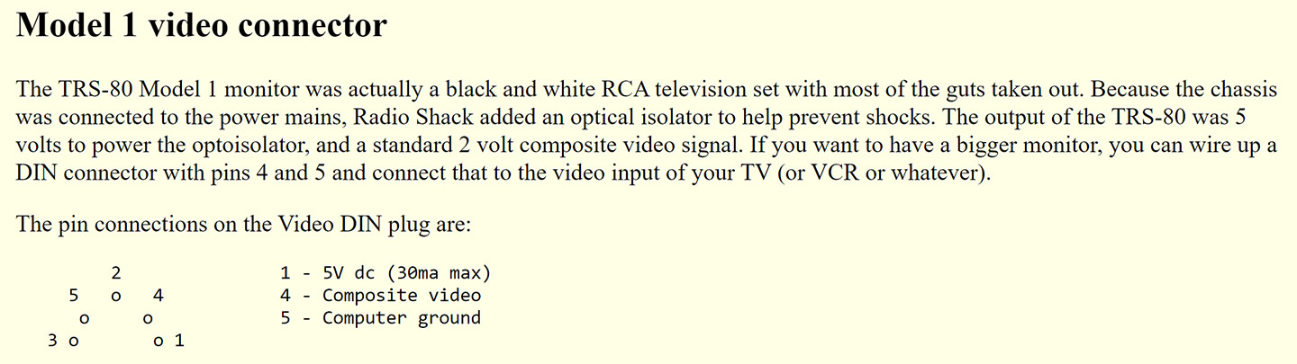
Although the monitor included with the TRS-80 is just a rebranded and stripped down RCA consumer set, the plug that the computer requires is not your typical RF or Composite but instead a 5-pin DIN. This means that plugging in a common monitor including modern LCDs is not possible, by default.
Since I hadn't had a functional TRS-80 to even test the monitor beyond knowing that it had a strong picture tube, I was unsure if perhaps it was just a horizontal or vertical adjust on the monitor itself that was malfunctioning. As the monitors themselves can also have sync defects. Adjusting the controls on the back of the monitor eventually managed to at least get a marginally decipherable display but it was still slowly scrolling one way or another and impossible to fix to the screen.
It doesn't take much effort to wire up a new composite cable so that it can be plugged into any device. This is my preferred approach at this juncture so that I can test the TRS-80 on a knowingly collaborated monitor. This will prove beneficial for many reasons down the road including for alignment and potential screen capture reasons.
I built a couple different cables using ordinary 5 Pin DIN Male Plugs and composite cables. I had some with a thicker and more insulated video cable and others that were just your common RCA style. It was just a matter of soldering the ground and signal from the cable to the correct pins. There is an in-depth explanation and video at the incredibly thorough Ira Goldklang's TRS-80 Revived Site. Note that there is a small verbal slip-up in the video when pointing to pin 4 vs. 5, so pay attention to the actual pin-out and read the comment from Patrick in that video for clarity. (One could also create the inverse of this cable to convert the TRS-80 monitor's 5-pin to a common composite to then enable use of the set for any device.)
Homegrown composite cables of respectable length, to enable TRS-80 hookups to any ordinary display. Note that I used a white stereo cable for one of them simply because it was a loose cable I had around, but it is acting as a video (yellow) cable here.
With that done, I could attempt to rule out the monitor. When plugging it into any digital LCD display, I realized it was failing to catch sync signal enough to even detect output. Since analog CRTs are more forgiving with sync problems, I tried a couple other knowingly collaborated sets here and saw the same tearing and scrolling problem where it just wasn't taking horizontal hold.
On-board Adjustment Pot Failure?
The TRS-80 has two 100K variable resistors to adjust the horizontal (R20) and vertical (R21) centering. If these have failed or are poorly adjusted it is possible that could be interfering with the rest of the sync operation, as seen in the schematic below.

The TRS-80 schematic depicting the video output section (top) and sync section (bottom). Note the importance of R20 and R21 to manage the horizontal and vertical positioning.
I realized that the controls, in particular the horizontal one, were not actually impacting how the display was positioned or scrolling on the screen. The vertical was allowing some movement, but I could turn R20 to the extremes on each side and have no change on screen. A multimeter check of the resistors proved they were still technically functional, so I assumed this was not the problem. However, I once again wasn't a fan of how touchy the controls were, so replaced them with new horizontal ones. In fact I put the adjustments on the opposite side of the board. This may sound peculiar but it actually serves me better as they are now accessible directly by lifting off the top of the TRS-80 once assembled (albeit so were the originals from the side), and more importantly have no chance of being accidentally altered, which I found was happening while working at it originally..

The new and improved resistors still exhibited the same symptoms of inability to manipulate the output signal, which was a scrolling mess.
IC Failure in the Sync Circuit?
Alas we arrive at the most common culprit, one or several failed IC chips along the sync path. However, as a consequence of the prior troubleshooting, some nice composite cables have been constructed and now all four variable resistors on the board have been replaced with more structurally sound versions.
As the Radio Shack technical handbook notes, the sync generator is one of the easiest systems to troubleshoot. The schematic shows that we mostly have to deal with Z5, Z6 and Z57 as the interconnected ICs integral to the successful sync-up to grab horizontal/vertical hold. None of these chips are socketed by default, but I prefer to add sockets to each as I remove and replace. If you have an oscilloscope and logic probe you can more intricately troubleshoot the pins of these chips and compare to the expected results from the data sheets and schematics.
These are fairly common 74C00 (Z5) and 74C04 (Z6 and Z57) chips. In my scenario after additional troubleshooting it was determined that Z6 was the true culprit, although others who experience this may find Z5 or Z57 to be contributing factors. If you have spares, these three chips are probably worth socketing and can then pinpoint the problem by substitution. I wound up socketing all three of them.

Replacing ICs Z5, Z6 and Z57 will most likely resolve the horizontal tearing and inability to lock the display to the screen.
With these chips replaced, finally we get a solid screen hold and the output is legible. We will worry about centering the display precisely later on when it's actually functional, but for now you can adjust R20 and R21 in combination with the vertical and horizontal controls on the monitor to get the display approximately aligned for your display. Be careful as moving any of these controls to an extreme value will cause the sync to be lost again, so you'll probably want to start with an approximate midway point on each of the controls and work from there. Once you've experimented enough with the four controls and how they relate to one another, it gets pretty easy.
TRS-80's Own BSOD - Garbage Screen
If all is well, powering on a standalone TRS-80 will take you to a BASIC prompt. Depending on whether the system has LEVEL I or LEVEL II cassette BASIC, you will either see a "READY" or a "MEMORY SIZE? / MEM SIZE?" prompt. If something is still technically faulty, however, you'll instead see something less appealing. One of the more common experiences will be that the display shows a full screen of corrupted characters. Although I didn't carefully document the evolution of troubleshooting these video problems, I will run through a few of the more simple troubleshooting techniques to attempt resolution.
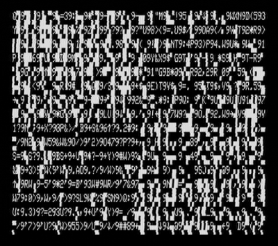
A typical example of a "garbage screen" that may appear on the TRS-80 if something has gone wrong (or...if you have an expansion interface connected but no disk drives).
Bad RAM?
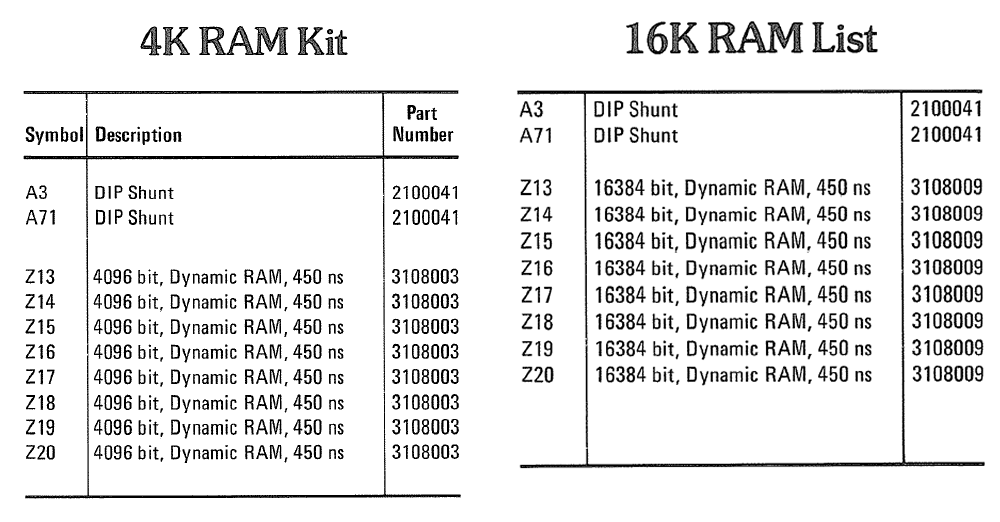
 The 4K and 16K RAM chips of these early sets are delicate. Since each of the eight chips contributes a bit of the overall RAM, one bad chip can result in these types of garbage displays. The TRS-80s were designed to support RAM replacements and upgrades, including by general Radio Shack dealers, so the eight RAM banks (Z13-Z20) will already be socketed. First you should do a simple touch test on the backs of each IC to verify that none of them are hot. If you find any that are hotter than the others it is a good reason to believe something is damaged within that chip or in the downwind of those feeding into it. You should use a multimeter to check that each RAM socket is getting the proper voltage at the correct pins (-5V @ Pin 1, 12V @ Pin 8, 5V @ Pin 9).
One extremely valuable hardware tool to have in one's arsenal for vintage tech repair is a dedicated DRAM Tester. These can be purchased for less than $30 on eBay and allow you to very efficiently test every bit of 4K through 256K RAM chips. I have worked this utility into my standard testing procedure for all new acquisitions where the RAM is socketed and easily removable. Finding out that the problem is just a bad sector of RAM can really simplify the troubleshooting path. The tester I use, on eBay, is titled "DRAM Tester for 4027/4096/4108/4116/4516/4816/4532/4164/4128/41256." You simply put one chip at a time into the correct slot, hit the test button, and it will cycle read/write of every bit of RAM and indicate the success or failure by four LEDs.

A simple 4K-256K DRAM tester. When all bits of a RAM chip are good the four LEDs glow blue, if bad they glow red.
Since 6604 (4K) and 4116 (16K) RAM chips were common on many 8-bit systems, it is easy to acquire quite a lot of it from repairs and part machines or to source it online. The TRS-80 is forgiving with their speed and the specs indicate that 450 ns or higher is fine. Even if you don't have the RAM tester and nothing feels hot to the touch, if you have a set of known working compatible RAM chips then substituting them is a quick process. You can find IC extractor tools like the PHONSUN PLCC for under $10 that can make it easier to extract the chips, but just a small flat-tip screwdriver or dental tool sliding carefully under one side and then the other is adequate. Be very careful to pull the chips straight out and to loosen them from the sockets before yanking them out, or you'll easily end up with bent or broken pins.
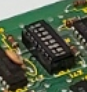 UPGRADING FROM 4K TO 16K - SHUNT INFORMATION: If the stock configuration of your TRS-80 has only 4K, I'd recommend upgrading to 16K to vastly expand its capabilities as required for many games and applications. This is easily achieved by simply substituting the RAM in Z13-Z20 and updating the Z71 SHUNT. This 8-row shunt has to reverse the open/shorted positions for rows 1-6 to embrace to 16K mode, as seen in the table below from the Sams reference book. Rather than attempting to reuse the original shunt by soldering bridges and making cuts, just swap it out for a standard 16-pin DIP switch and set the corresponding "Open" states to "Off" and "Shunted" to "On." If your system already is configured with 16K the original shunt should already match the necessary 16K configuration so is safe to leave alone.
To upgrade a TRS-80 Model I from 4K to 16K, the Z71 RAM SELECT SHUNT has to be modified. The easiest solution is to replace the shunt with a standard 16-pin DIP switch and set each switch accordingly.
It is also possible to do rudimentary RAM checks through simple BASIC scripting, provided you can get to the point of executing such code and reading the output. One such example of this can be seen here in which you specify a starting and ending memory address (decimal) and then the program sequentially writes 0-255 in every byte and reads each value back to ensure it was successful. This utility can take a very long time, hours to check 32KB, and really is no comparison to testing the RAM with the incredibly fast dedicated tester. Iterating 256 times per byte is also excessive when trying to get a rough gauge on any bad RAM, you could revise the loop to just a couple intervals or even a static number and have it perform much faster, though still really slow by comparison.
Here's a memory map (HEX, Decimal, Purpose, Capacity), for reference:
- 0000-2FFF (00000-12287) - Level II ROM (12,287 = 12KB)
- 3000-37DF (12288-14303) - Unused (2,016 1.97KB)
- 37E0-37FF (14304-14335) - Memory Mapped I/O (32 = 0.03KB)
- 3800-38FF (14336-14591) - Keyboard Map (256 = 0.25KB)
- 3900-3BFF (14592-15359) - Keyboard 'shadow'ed here) (768 = 0.75KB)
- 3C00-3FFF (15360-16383) - 1KB Video RAM (1,024 = 1KB)
- 4000-41FF (16384-16895) - RAM used by the ROM routines (512 = 0.5KB)
- 4200-7FFF (16896-32767) - Usable RAM in a 16K Machine (15,872 = 15.5KB)
- 8000-BFFF (32768-49151) - Additional RAM in a 32K machine via EI (16,384 = 16KB) - Z9 to Z16
- C000-FFFF (49152-65535) - Still more RAM in a 48K machine via EI (16,384 = 16KB) - Z1 to Z8
Bad CPU?
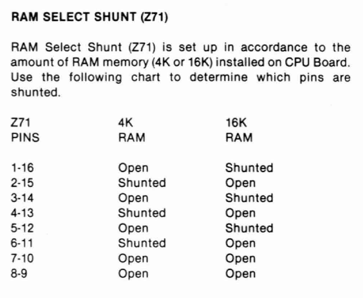
 The Z80 CPU is similarly easy to troubleshoot, at least at a high level. Rather than wasting time diagnosing each pin and comparing the states to the expected results from the logic charts and schematics, the CPU is common enough that simply substituting it with another known working one can alleviate much of the time of ruling it in or out as a culprit. If you have a different Z80-powered device, you could swap the TRS-80 CPU into that and see if it still runs without issue as a crude method of verifying minimal CPU functionality. Note that different platforms utilize the Z80 in different ways, so not every potential problem with a Z80 might be detected if trying on different platforms. If you want to get even more meticulous, there exists Z80 Tester tools (PCBs and fully assembled) similar to the DRAM tester I explained above.
A simple dedicated Z80 CPU tester, photo by taunus_osi on eBay.
Bad ROM?
 The ROM chips themselves can be responsible as well. If you pull the ROM chip (or ribbon cable that leads to the daughter board in the case of Level II upgrades), or more simply remove Z3 SHUNT, then power up the machine with known working RAM and CPU, you should get a screen full of flickering @9 symbols. This means that everything checks out nicely including address lines 0-9, up to the point of communicating with the ROM, which would make that the next good candidate to troubleshoot, preferably by substitution.
Relatedly, if you are able to remove the Character Generator (Z29) the screen should show squares for every character. If there are still odd glitches, half-shown squares, or other strange things then the problem stems somewhere outside of the character generator.
Pages 63 through 75 of Radio Shack's TRS-80 Technical Reference Handbook (2nd Ed.) guide cover much more detail on how to isolate sections of the circuitry to narrow down issues including this sort of video corruption. "If you get @9's on the screen, you probably have a ROM error. If no @9's or partial @9's are visible, you could have video chain or video RAM problems."
In a later section of this article I will describe the process I used to upgrade my ROM to Level II v1.3 using substitute EPROMs.
Expansion Interface Bus?
 When an expansion interface is connected to the TRS-80 and powered on, turning the TRS-80 computer on will show a garbage screen while seeking data from a floppy drive. If not floppy drive is attached, the screen will be stuck in this state. Pressing the RESET button will attempt another seek of floppy data.
If no expansion interface is connected (and I highly recommend beginning your TRS-80 troubleshooting adventure with nothing else connected except the core TRS-80 computer) there is still a chance something along the expansion interface bus is triggering this garbage screen behavior.
To override any phantom expansion interface (or an actual EI if one is connected and powered on), hold down the BREAK key and then power on the TRS-80. You may have to attempt this several times. If the problem resides somewhere within the expansion interface communication line, the garbage screen should flash off and get you to the original BASIC prompt. You can also try holding in BREAK and RESET when the garbage screen is already displayed, but I recommend doing the hard power cycle.
If this resolves the problem, then we know that the RAM, ROM, CPU and overall system is relatively healthy. It then becomes a quest to pinpoint precisely why it believes an EI is connected when one is not. Scrutiny should be placed in checking for any dry solder joints, bridges or other unusual characteristics of the board especially surrounding the expansion interface bus and components. This is all assuming that the CPU, RAM and ROM are good based on the previous checks. You'll want to parse through the technical guide and Sams schematics to understand the flow from CPU/Keyboard to Expansion Interface and the various ICs that get touched along the way

Simplified block diagram from the TRS-80 computer to the Expansion Interface from Sams.
Character Corruption - Video RAM (2102) or Character Generator
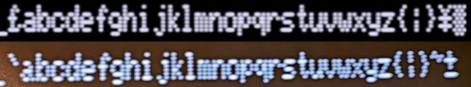
If you overcome all previous defects based on the strategies above or your own discovery, you will hopefully arrive at the BASIC prompt and see that the system is able to at least minimally be interacted with. However, as I discovered in the evolution of my repairs, the characters were clearly corrupted on my screen. They were technically all being output correctly, but "Rs" showed as "Qs," "Ds" looked like lightning bolt glyphs, and so on. Only spaces and underscores were showing suitably.

LEFT: The display I eventually arrived at after resolving other conflicts, clearly a LEVEL II v1.2 or lower BASIC prompt. RIGHT: What the characters should say, instead.
This generally comes down to either a problematic flip/flop IC (Z28), character generator (Z29) and/or most often one or more VRAM chips (Z45-Z48, Z61-Z63). The character generator is an obscure chip these days and, short of rigging up a custom EPROM for it, is best to rule the other possibilities out before attempting replacement. If your system doesn't already have a lowercase mod, I would recommend adding one which will make for a better system and might resolve the character issue. If you buy from Ian he includes a fresh character generator with descenders. More on lowercase modifications, later.
The video RAM sockets are not socketed so to replace them you'll have to desolder, add sockets and then replace. [Some later runs of the TRS-80 did include a socket for Z45 as a convenience for Radio Shack technicians or users to add a lowercase mod.] But before you deal with any of that, read on.
The Sams manual includes a clever bit of BASIC that allows checking of each VRAM bit without needing to remove anything or use external tools. The code is below:
|
1 2 3 4 5 6 7 8 9 10 11 12 13 14 15 16 17 18 |
REM VIDEO RAM TEST PROGRAM 5 DATA 1, 2, 4, 8, 16, 32 , 128 10 Y = 6: X = 15360 : POKE X,64 20 IF (PEEK (X) AND 64) = 64 THEN 30 ELSE 150 30 POKE X,160 40 IF (PEEK (X) AND 64) = 0 THEN 50 ELSE 150 50 FOR X = 15360 TO 16383 60 FOR Y = 0 TO 6 70 READ Z: POKE X,Z 80 IF (PEEK (X) AND Z) = Z THEN 90 ELSE 140 90 POKE X,O 100 IF (PEEK (X) AND Z) = 0 THEN 110 ELSE 140 110 NEXT Y 120 RESTORE : NEXT X 130 PRINT " MEMORY GOOD " : END 140 IF Y = 6 TH EN Y = 7 150 PRINT " BIT "; Y; " OF MEMORY LOCATION" ; X; " CHECKS BAD" 160 IF Y = 6 THEN 50 ELSE 110 |
For your convenience, I've created a ZIP file containing both a .CAS and .WAV version of the same code. You can feed the .CAS file through Play CAS from a computer or laptop to the TRS-80 cassette interface by plugging the black (Audio INPUT) end of the TRS-80 cassette cable into your Headphone (or Front Audio Out) jack of PC. Or, you can play the WAV file from any audio source into the TRS-80. To load it on the TRS-80, assuming your keyboard is functional, type CLOAD at the Level II BASIC prompt and press ENTER. Then play the audio file. It should take about 11 seconds and when done you can type RUN and press enter.
The program will iterate through every byte of video RAM and when done with each will output an "@" character to the screen. If there are any errors along the way it will mention what bit(s) check bad. You can use that and a little math alongside the schematics to figure out which chips are defective. To quote from an 1980 Radio Shack technician (Marc Brumlik):
Ram errors are the most common video problem. To isolate the defective chip, first determine the ASCII code of that character that should be shown and the character that appears instead. For example, a blank screen (press CLEAR) is filled with ASCII code 32's (the code for a “space”). If some location shows a “$”, which is ASCII 36, subtract 36-32=4. The location with the error is displaying character 36 instead of character 32 because bit 2 is stuck on (2^2=4). Replace Z46. Similarly, if pressing “B” on the keyboard displays “J” on the screen: B=66, J=74, 74=66=8, and since 2^3=8, replace Z45.
Of course if the entire display is corrupt, you'll have to get a little more creative to decipher the results. In the event that you have an actual printer hooked up to the machine, replacing PRINT with LPRINT in the code (lines 130 and 150) will output correctly to the printer instead. Below is the basic ASCII chart of characters for Model I, taken from the book Learning TRS-80 BASIC by David A. Lien.
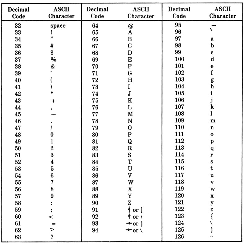
The basic TRS-80 ASCII chart for Model I (excludes higher coded special glyphs).
Note again that lower case characters won't render without a lowercase mod. In any case you should be able to compare the on-screen characters with the intended characters to create a key of sorts to understand the discrepancy. Below is a generated ASCII table and output from a TRS-80 for ASCII 33-90, which are important characters including for the VRAM check output.

Partial ASCII table generated from a TRS-80 for characters 33-90.
The code below will produce the same table as the screenshot above, so you can run it on your defective machine to simplify comparing the differences.
|
1 2 3 4 |
5 CLS 10 FOR N = 33 TO 90 20 PRINT N;"= ";CHR$(N);" "; 30 NEXT N |
Again, here is a .CAS and .WAV file for your running convenience. Finally, you can refer to the Wiki table of the TRS-80 character set for a more complete chart.
Sometimes you can also troubleshoot bad RAM/VRAM by piggybacking a known good one carefully onto a bad one to see if anything changes on screen. Since replacing all the VRAM is more of a process than just swapping them out due to the lack of sockets, if you can manage to resolve the character problem by avoiding as much of that as possible it'll be much less of a hassle. If you exhaust the possibilities of checking and replacing VRAM or the glitches are more strange than just character substitution, then consider Z28 and Z29 replacements. With Ian's lowercase mod the 8046673 (SCM37530P) character generator is included, which fixed issues with earlier character ROMs and includes one line descender characters for lowercase.
Malfunctioning Keyboards
After I had resolved the major underlying problems with the system, I still was unable to use the keyboard very well. There are two versions of keyboards for the Model I. The original was more rigid as a singular mold with two thin metal pieces inside of each key. These metal fingers would come together and short as the button was pressed down. The other keyboard style was a much more common ALPS switch style that is generally more dependable and easy to repair.

The two versions of keyboards found in TRS-80 Model I sets.
The set that I was repairing had the original non-ALPS style. These were notorious for causing keybounce especially after repeat use or in dirty environments where the small contacts lost their conductive properties. Some of the keys I tried didn't work at all, while others would spam 2-6 of the same letter with one keypress and other times would only work on occasion or with a lot of pressure.
To verify that it isn't a circuitry issue, you can review the bottom of the keyboard's solder points and manually short the two leads for any given key, which should send a pulse to the computer's ROM and show the corresponding key on screen. If any of the keys fail this test, checks should be made for dry or faulty solder joints. Since I had a number of keys not responding at all even in this method, I ended up reflowing the solder points for every point on the keyboard.
Cleaning the Old Keyboard
For this keyboard, I removed all the keys and gave them a good cleaning in soapy water. For the metal contacts I first used compressed air. Then gently went over them with a small foam pad of isopropyl alcohol and then contact cleaner (e.g., Deoxit). In the process for the problematic keys I'd also depress the keys a bit to work in the cleaner more. This is really about the extent that these keyboards can be cleaned. Great care must be taken not to bend or break the metal clasps.
After getting everything back together, the keys were almost entirely functioning well again. Several required more attention to straighten the metal contacts that had gotten warped. The spacebar had a bigger problem in that one of the metal contacts appeared broken in half so no contact was ever being made. To remedy this, I had a spare broken keyboard of this same style. The metal contacts have to be desoldered from the bottom of the board. Then, using a tight grip tweezers or similar, grab onto the metal finger and pull straight up from the top. After some amount of effort I was able to replace the broken contact with a new one, and resolved this spacebar issue.
Keybounce is something that plagued TRS-80s even with good keyboards, due to software oversights in the ROMs. There were some software fixes but it wasn't until Level II v1.3 that the debounce routines were remedied to rid the system of this problem even with somewhat faulty keyboards. That said, my repairs and cleaning of the contacts were dependable enough that I rarely experience keybounce in Level I or Level II ROMs including those that predate 1.3.
Replacing the Worn Ribbon Cable
 While working at a TRS-80, one of the main frustrations is how the keyboard is permanently affixed to the mainboard through a delicate 20-pin foil ribbon. The slightest twist of either half of a disassembled TRS-80 can tear this ribbon or cause the foil to crumble away. Although I spent a lot of time working around this problem, eventually I decided to replace the ribbon with a detachable solution.
This is easily achieved using 20-pin 2.54mm right angle headers. You can buy a pack of 40-pin ones for $7 on Amazon and then snap one in half for use here. The part that requires the most caution is removing the old and corroded pins from the main board. I have found that the traces on the slot edge are easy to lift if you apply too much heat or too much force trying to extract the pins. A lot of flux and even reflowing the solder to then suck out, while ensuring the residual pins are straight before pulling them upward, will help. You can also use straight headers or mix and match both, but be careful as there is only so much height available under the case.
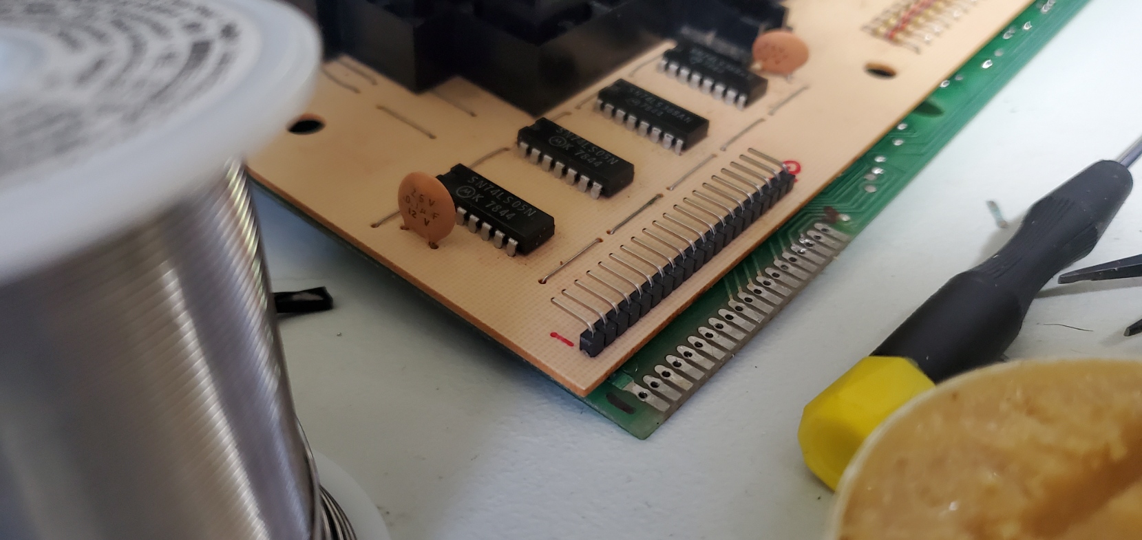
The keyboard connector has been replaced with a right angle header row, to ensure adequate room to close the case.
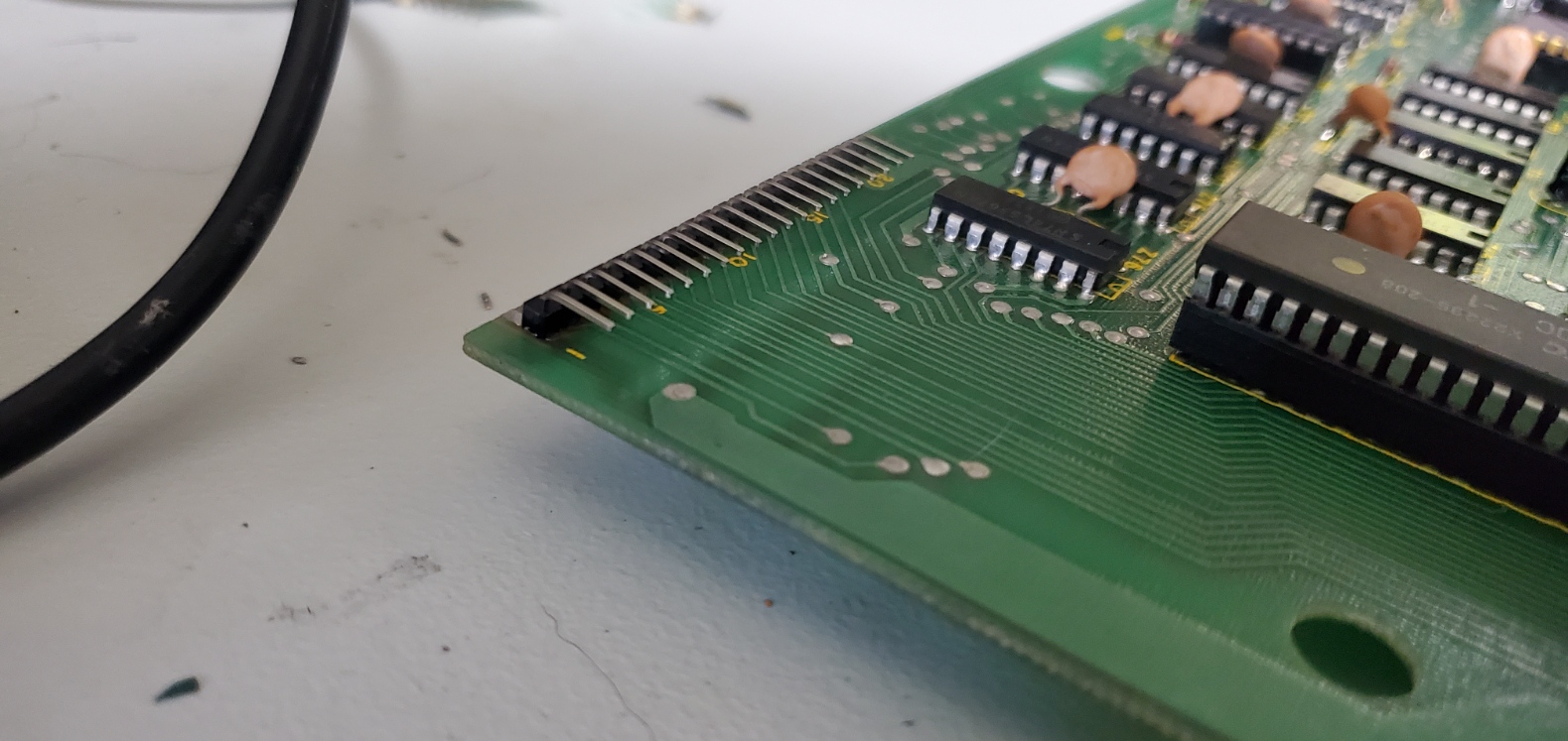
The pins on the mainboard have also been replaced with a right angle header row.

Using a standard keyed 40-pin IDE cable, the unkeyed side can easily plug into both sides of the board to complete the fix.
For the cable itself, I went through a cable bin and found an old keyed IDE (PATA) cable, in which one pin hole is filled in to avoid accidental reversal in hard drives. This serves a convenient purpose here, as we only want to use one row of the 40-pin cable anyhow. By using this keyed style we will not be able to accidentally plug the wrong half of the pins into either side. I made note on the keyboard's PCB where pin 1 and pin 20 were for visual reference. When plugged in, the red side of the IDE cable will go toward the edge of the PCBs on both sides — you want to make sure you don't twist the cable and plug one side in backwards.
With this update in place, the keyboard was confirmed to be 100% in perfect working condition. I tested it for weeks after the cleaning and saw no drop in performance. The TRS-80 does not need a keyboard connected to function. If you have Level II ROM and turn it on with no keyboard attached, you will likely see a key such as a parenthesis and then new line repeated over and over. Even at that, when replacing components and testing the basic workings of the system it can be relieving to not need a bulky keyboard connected at all times.
More About Lowercase Mods
To cut costs, the Model I internals include space for only seven VRAM chips (Z45-Z48, Z61-Z63) in which six bits control the character display (from 2x3 matrices), the seventh is skipped and the eighth is for toggling between character or graphic glyphs. Even though the character ROM had lower case glyphs embedded, there was no direct way to access them on an unmodified unit. Matthew Reed's TRS-80.org website explains the history of this in much more depth including details on the popular Electric Pencil mod that was sold to remedy this problem. There were other official and homebrew mods similar to this as well, as detailed on page 106 in the excellent book: "The Custom TRS-80 and Other Mysteries (1982)"
If you open your TRS-80 set and see a double-stacked bit of VRAM (usually in Z45 or Z46) with some bodge wires or other things happening around Z29-Z30, it's a pretty safe bet that you have some version of the lowercase mod. Sometimes these modifications would connect to a physical switch mounted to the exterior of the case, so that the extra VRAM/bit could be toggled on or off. The original Electric Pencil mod called for the addition of a control key as well, which was used in their word processing software. In that program, lowercase was toggled using SHIFT + BREAK. Their manual explains the lowercase dilemma very well:
The TRS-80 video display uses a dedicated block of 1024 bytes of memory located in memory space at 3000 Hex. When received from the factory, there are only 7 memory chips installed in this block of memory, providing 128 possible characters for screen display. The stock TRS-80 uses 64 of these combinations for graphics and a second 64 for the upper-case subset of the ASCII character set. Bits 0-5 control the character selection, and the highest bit (bit 7) is used to determine if the character is alpha-numeric or graphic. Bit 6 is missing!
To add lower-case display, bit 6 must be implemented. This may be accomplished by switching the memory chip for bit 7 to bit 6, thereby enabling lower-case letters and eliminating graphics, or by addition of an 8th memory chip. We prefer adding the extra chip. In either case, if you plan to use Level II BASIC, you must include a switch to disable bit 6, or BASIC will place a lot of funny characters on the screen!
Although it was stated that a toggle switch should be added, that was mostly with respect to the very original character generator IC. Since lowercase kits and later models began shipping improved character generators and mappings, this concern quickly grew out of style. The odds of running into any clashes with a permanent lowercase mod is non-existent unless you do happen to have the original run Z29 IC. If you feel compelled to add a switch, it's also a trivial process as detailed in the Electric Pencil instructions.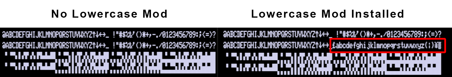
Inside of the Custom TRS-80 book, the following code snippet is used to iterate through all 256 character values and POKE them to the screen. This is a way to verify whether your device has lowercase installed.
|
1 2 3 4 5 6 |
10 CLS 20 FOR X = 15360 TO 15360+255 30 POKE X, Y 40 Y=Y+1 50 NEXT 60 GOTO 60 |
Here's the .CAS and .WAV. As you can see from the screenshot, when all 8 VRAM bits properly functional, you'll be able to output the lower characters from the ROM, otherwise the original all-caps set will be repeated.
Lowercase Driver
Even with the hardware mod complete, by default Level II BASIC and other variants of OS will not enable you to write lowercase without loading a driver of sorts. This was supplied within Radio Shack's conversion kit for both BASIC and disk systems. A copy of this driver can be found here:
Two different files are included in the ZIP file. The BASIC version can be loaded by entering SYSTEM <ENTER> U <ENTER> and then playing ULCBAS.CAS. In about 20 seconds it will finish and you can then press / to reload BASIC but with lowercase capabilities. This will have to be done every time you want to work in vanilla Level II BASIC and utilize lowercase. To toggle the lowercase feature on-or-off, press SHIFT + 0. The other file, ULCDVR.CAS is for very old disk systems, but as most DOS platforms for TRS-80 include their own integrated lowercase driver, this is largely redundant.
Although not every application or game embraced lowercase, the difference in readability by those that did is substantial. This is especially true in text adventure games, such as Scott Adams' Adventureland (available from Ira Goldklang's TRS-80 website). In fact, Scott and other developers make selective use of CAPS within their content to add to the atmosphere and dynamics, in ways that users without the lowercase mod miss out on.

Differences in Character Generator ROMs
 Throughout the TRS-80 lifecycle, a few official and numerous homebrew iterations of the character ROM were manufactured. The original (MCM6670) was not particularly meant for lowercase since by default no device supported it. All lettering on this original ROM aligned at the base, even lowercase letters that were meant to have descenders. This led to some strange screen display and also included an additional glitch that became known as the 'flying a' bug. Eventually the one shipped with kits and newer devices was MCM6673, which reworked the font to support one-row descenders and is the one you should pursue to remedy the early defects.
There is also a chip dubbed Gendon3 that permits three-line descenders, which Ian also sells on eBay but is more of a project to mod than the original Radio Shack / Electric Pencil style. You can see what that looks like in the screenshot to the right (credit to Ian), or read more about it on this thread from Ian on VCFed.
 I have both the MCM6673 mod kit with great thanks to Ian, but also a custom EPROM (MSL2716K) on its own breadboard that was included in one of my part machines. I haven't done great analysis on the EPROM yet or if this was actually a distributed kit, but it sports a few different glyphs such as a ` in place of the Euro sign, and the two on the end. The typeface itself matches the 6673 including one line descenders.
TOP: The MCM6673 style Character Generator ROM. BOTTOM: A custom EPROM that features a few different character glyphs but otherwise the same character font with descenders.
For the most extensive rundown of "everything you need to know" about lowercase mods, past and present, please refer to page 25 of the TRS8Bit Newsletter, Volume II Issue 03, September 2017. In that article, Ian Mavric does an exhaustive rundown of these character generators (page 137 of the Year 2011 bulk PDF, and Part 2 on page 188 which delves into third party mods).
Level I and Level II BASIC ROM Versions
The original TRS-80 shipped with "Level I" BASIC, which was derived from Tiny BASIC and very limited compared to their soon licensed Microsoft BASIC, dubbed Level II. Level II itself saw several updates over the life of the Model I, which were later coined as v1.0, v1.1, v1.2 and v1.3. For a thorough study of the differences among them, I differ you to Matthew Reed's website:
- Level I BASIC: Features and History
- Level II BASIC: Features and History
- Level III BASIC: Features and History
- Level II BASIC: ROM Differences
Although Level III BASIC was technically a thing, it wasn't a ROM-based solution and not widely adapted. As such, the best Cassette BASIC ROM solution for Model I is v1.3.
Until the later era of Model Is, Level II was typically supplied as an upgrade that used a three-ROM daughter board attached to one of the two ROM slots on the mainboard. Eventually it was also made available as a two ROM set that could plug directly into the main PCB, alleviating the need for any ribbon cables and sub-boards.
Determining ROM Versions
 By chance I happened upon a very compact snippet of code in the 1982 book "TRS-80 Assembly Language Made Simple" that does a few PEEKs to arrive at a number that can determine the version number.
|
1 2 3 4 5 6 7 8 9 |
1 REM TRS-80 ROM CHECKER 2 REM RUN PROGRAM AND WAIT FOR OUTPUT NUMBER 3 REM 176 = ROM 1.0 4 REM 142 = ROM 1.1 5 REM 10 = ROM 1.2 6 REM 162 = ROM 1.3 10 FOR I=11264 TO 12287:V=PEEK(I):S=S+V:NEXT I:X=S/16 20 A=(X-FIX(X))*16:Y=FIX(X)/16:B=(Y-FIX(Y))*256 30 PRINT (A+B) |
Here's a .CAS and .WAV version of this snippet. This program will take a minute to RUN and will return a three digit number.
- 176 = ROM Version 1.0
- 142 = ROM Version 1.1
- 10 = ROM Version 1.2
- 162 = ROM Version 1.3
That aside, the most definitive resource for reviewing and comparing ROM sets would be Ian Goldklang's website. Although it is noted that TEST1A from TRSDOS can determine this if you have a fully functioning expansion interface, disk drive and TRSDOS disk, I find the alternative method of running a simple BASIC program to be faster and less error-prone. The code for this script, written by Dean Bear, is reprinted below along with CAS and WAV formats. It is faster than the snippet above and more comprehensive.
|
1 2 3 4 5 6 7 8 9 10 11 12 13 14 15 16 17 18 19 20 21 22 23 24 25 26 27 28 29 30 31 32 33 34 |
1 FOR I = 0 TO 23 : READ P : POKE 28656+I,P : NEXT I 2 DATA 17,0,0,62,16,237,71,33,0,0 3 DATA 69,26,79,9,19,237,87,186,32,247 4 DATA 195,154,10,201 5 POKE 16526, 240 : POKE 16527, 111 6 DIM ROM(3) : ? "M1 ROM CRCS FOR 3 CHIP SET" 7 FOR I = 0 TO 2 8 B = 16*I : C = 16*(I+1) 9 POKE 28658,B 10 POKE 28660,C 11 D = USR(0) 12 IF D<0 THEN D=D+65536 13 ROM(I) = D 14 A$ = "ROM "+CHR$(65+I)+" = " 15 GOSUB 22 16 NEXT I 17 ? "CRCS FOR 2 CHIP SET, USE A/B AND C VALUES" 18 D = ROM(0)+ROM(1) 19 A$ = "ROM A/B = " 20 GOSUB 22 21 END 22 S=16:X=2 23 IF S<D THEN X=X+1:S=S*16:GOTO 23 24 PRINT A$; 25 T=D 26 FOR L=X TO 1 STEP -1 27 N=INT(T/S) 28 A=0 29 IF N>9 THEN A=1 30 IF L<5 THEN PRINT CHR$(48+N+7*A); 31 T=T-N*S:S=S/16 32 NEXT L 33 PRINT 34 RETURN |
.CAS and .WAV versions, here.

Upon running the CRC checker script in Level II BASIC, the resultant can be compared at Ian's website to determine ROM version number. The values above reflect Level II v1.3 ROMs.
From the various parts and pieces I acquired this past year, I had several different ROMs. After running the checksum code above, I determined I had both v1.0 and v1.2, as well as some unknown EPROMs in various states of decay, and the original Level I. To get the best of both worlds, Level I ROM can remain in one socket (Z35) and the daughter board with Level II can run from Z36. A switch can be added to toggle between Level I and Level II as explained on pages 112-114 of the Custom TRS book.
With that done, I still preferred to replace Level II v1.2 with v1.3 to embrace its advances in both cassette loading accuracy and keybounce prevention. Obtaining original ROMs of v1.3 is not an easy task, so the solution is to burn custom EPROMs.
Custom EPROMs for Upgrading to Level II v1.3
 [Addendum: While my approach below is built around 1980s tech including the EPROM chips and ROM files, you will find a similar technique outlined by Matt Boytim, using the much more common 27256 EPROM, on Page 9 of the Dec. 2021 issue of TRS8Bit - "Replacing Model I ROMs with A Single 27256 EPROM"]
Throughout months of repair efforts, I'd been mentored by Larry Kraemer who contributed a lot of time and energy toward advancing my TRS-80 knowledge. Larry wrote excellent articles and solutions in TRS-80 newsletters from the earliest days of the Model I onward, and remains actively supportive to this day. You can find Larry on the VCFed forums and he kindly offers a wealth of wisdom about the TRS-80 line of machines.
One article that Larry wrote in the early days and republished with amendments in TRS8Bit Volume 08 Issue 01 (March 2014) was: Radio Shack Level II ROM UPGRADE to Version 1.3 (starting on Page 13).
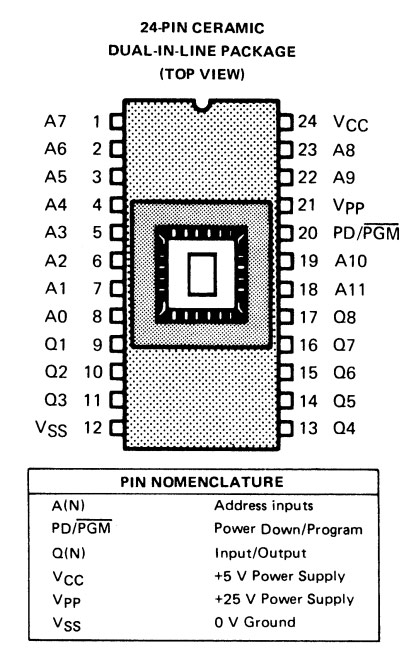
The gist of the solution is to use three TMS-2532 EPROMs to burn copies of the v1.3 ROM (three 4K raw binary files). Those EPROMs have a near identical pin-out to the original ROMs, with the exception of pin 21. That pin does not get inserted into the sockets but rather connect to a pull-up resistor, to run them high, mimicking the behavior of the original ROMs.
Since this chipset requires 25V, attempting to burn it on modern lightweight (USB-powered) programmers like the TL866 II is not practical, nor do most modern programmers provide native compatibility with these 1970s-80s EPROMs.
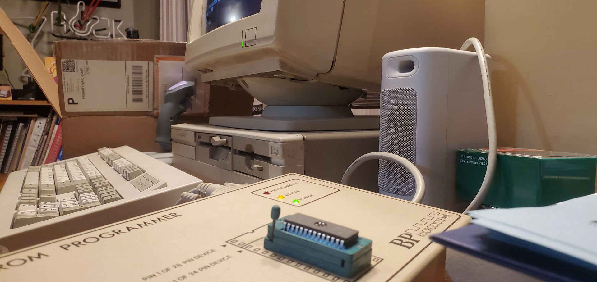
 Instead, I opted to use the BP Microsystems EPROM Programmer EP-1 from the 1980s. This is a ROM-based programmer that is entirely self-contained and can be utilized through any terminal-type software (RS232 serial interface) or its dedicated DOS software. A great guide on using it can be found on Paul Carbone's website, including links to the manual, latest software/firmware and a list of supported chips.
The firmware in mine was initially version 2.00 (1986) but they continued pushing out updates through the early 1990s with 3.20 to support an increasing list of programmable ROMS. I had some spare 27256 chips and was able to program the 3.20 ROM to it, then installing it into the device for a successful upgrade. There are a couple different versions of its DOS program, the latest of which works best on 286-486 MS DOS machines whereas the former was designed for PCDOS on XT machines. The EPROM software ran well on my IBM 5160, but the latest iteration to match version 3.20 had to be operated from my 286. If you are using a Serial-to-USB adapter on a modern machine, your success may vary depending on a lot of circumstances. I stuck with original era-accurate hardware to do the burning.
It is not difficult and requires only a few commands, a list of all the noteworthy ones I generally use include:
- EP 1 or EP 2 to launch the EP software, where # is the port number (1 or 2)
- TEST to walk through a detailed hardware test of the device which includes each individual pin check (requires multimeter, worth running once to verify the hardware is within spec)
- C to list and select the manufacturer and chip
- RB (Binary) or RH (Hex) or RI (Intel Hex) or RM (Motorola Hex) or RT (Tektronix Hex) to read the ROM data to a file
- BLANK to verify that the EPROM is blanked out (all 255s) and ready to be programming
- P (Hex) or PB (Binary) to program the chip from a local file
- VB to verify the chip contents by comparing to a binary file
- SU to read and calculate the checksum for verification purposes
- S to review the EP-1 status including firmware version and chipset configuration
- Q to quit the application
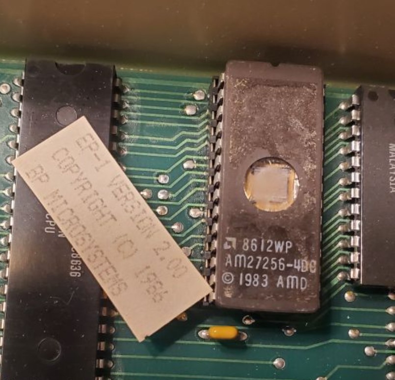
To create fresh copies of the Level II v1.3 ROMs, I programmed three 2532JL-45 EPROMS using the 1980s EP-1 programmer on a 286 CompuAdd computer, after transferring the necessary files via floppy and upgrading the EP-1's firmware.

After burning and verifying the three v1.3 ROMs, they were able to replace the v1.2. Pin 21 of A & B were lifted and soldered to a resistor to act as a pull-up.
With all of this in order, the TRS-80 was successfully booting to the new V1.3 ROM. The tell-tale sign that you are using V1.3 and not an earlier ROM iteration is that the initial prompt was changed to say "MEM SIZE?" instead of "MEMORY SIZE?."
Jittery or Unstable Video... Check Video Mixing Section (Caps & Resistors)
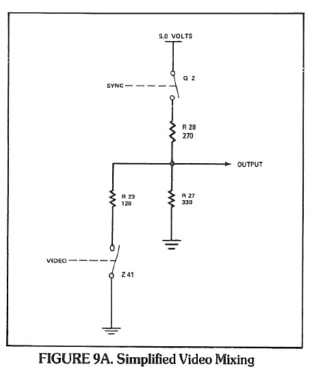 When I completed the majority of repairs to the point where I had a usable TRS-80, I still found that the display was wobbly, jittery and somewhat disorientating. My immediate reaction was that it could be the monitor itself. But I realized even when hooking to a composite setup the signal was just not steady, it appeared there was a lot of interference coming through the line. It's at this point you'd generally want to hook up an oscilloscope and analyze the actual video output signal to compare with what the technical references show. But at a minimum we should test the capacitors and resistors that are part of the Video Mixing circuitry. Since all other aspects are functioning fine including the character generation, horizontal and vertical mixing and sync generation, it seems to be something interfering after that point and before the signal gets fed out to the monitor.
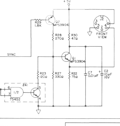 The Video Mixing section of the TRS-80 is explained well in the Radio Shack TRS-80 Technical Reference Handbook (2nd Ed.) on page 42-43. After ruling out transistors Q1 and Q2 (via substitution and testing), I recognized that when I removed ceramic capacitor C20 the video cleared up well but then we obviously lost the horizontal position. The manual notes: "Capacitors C7 and C2, together with R30, form a filter network for Q1 's collector." I checked the values of these and ultimately replaced C2 and C7 since I had an abundance of capacitors on hand. In that same pathway, I replaced a variety of the resistors that seemed to had drifted out of spec including R27-R30 and R22-R23. Since a lot of this also flowed through Z41 (75452) and I had some extras of that chip I swapped that as well.
These replacements, especially the resistors, helped bring the video back to perfect stability so there is no longer wobbling or drifting while in use. When I still had the board open, I took this opportunity to replace the rest of the electrolytics and a couple film capacitors since the majority of them are common and this helps future-proof those from drifting too far out of spec.
Triple Check IC Orientation, Work Environment and Cable Connections — A Word of Caution!
A lot can go wrong due to even slight carelessness when working on these systems. It happened more than a few times as I worked through the repair. A few really bad incidents and lessons learned included:
 When you accidentally insert an IC the wrong way... Sometimes when it's 4 a.m. and you're in a dim-lit space adding sockets and replacing chips, it can be easy to overlook the correct orientation for ICs. All ICs have an identifier for pin 1, usually with a cut-out at the top of that side or a dot/bump/marking where pin 1 resides. The PCB board also has a groove cut out to indicate where the top of the IC aligns. If you mess this up, a lot can get damaged depending on what chip you made the mistake on. In one occurrence by myself, I accidentally replaced one of the voltage regulators upside down and tried powering it up. This sent voltages to all the wrong pins and then to further areas of the board. In an instant the majority of 4116 DRAM had been fried and red hot to the touch. Even after remedying it, the process of retesting and verifying all components can be a real daunting prospect considering how many ICs and circuits cross paths.
 When you accidentally insert the power supply plug into the wrong socket... We already touched upon this issue earlier and I imagine this was a common occurrence in the 70s-80s given the identical cables and ports for power, video and cassette. The important takeaway is to not plug the live power cord into either the video or cassette ports, and ideally don't even plug anything into the wall until you have verified that each connection goes where it should. This mistake can result in stray voltage going everywhere that they shouldn't. The video port oopsie can lead to a surge and then no power/voltage, in which odds are the Zener Diode CR1 and/or regulator Z1 (possibly Z2) need to be replaced. Start with CR1. If you do the same with the cassette port, it can cause damage to parts along the cassette path. If this happens and suddenly the cassette line no longer kicks on or reads/writes, first try substituting the Z80 CPU and if that fails then check CR3, CR6, CR9, CR10, Z59, Z41, K1 relay...
 When you don't have a clean workbench and have metal tools laying all over it... Some people have massive wall-sized workbenches, others opt to do all their work from a cramped TV tray or computer desk 😉. Along with my recommendation of buying an anti-static work mat to avoid accidental discharge into the chips, it is essential to keep the surroundings clear from any potentially conductive material. Again speaking from personal mistakes, there'd be times I was working at this and suddenly see smoke, hear a pop, or everything just fails. At one point this happened when I was messing with the big power transformer Q4. In that instance and several others, I lifted the board up from the table only to discover a small screwdriver, wire cutters or pry tool had gotten under there and was making contact with numerous points, creating connections to components that never should be. If this happens you'll have to spend time tracing any potential problems yet again. At one point I had a bridge rectifier go out that I attribute to inadvertently shorting some connection points.
Centering the Video Output and Final Checks
Alas, we've reached the point where the entire TRS-80 Model I is back to peak form (right? right?!) and the final remaining thing to do is to fully center the video and do a last check of voltage before putting it back together.
First, check and adjust the voltages once more as described in the "Voltage Checks: Internal Voltage" section early on in this article. There is quite a range of tolerance so anything from 11.4V to 12.6V in the 12V line and 4.75v TO 5.25v in the +/- 5V lines are acceptable. The OCD side of me still prefers to get each value right on the mark at 12.0V and 5.0V. Now is also a good time to do the touch test on all ICs in the device to make sure none of them are running red hot, although some of the power transistors (especially the heatsinked ones like Q4) will, by design, run very warm. In my final phases of testing, I found that Q3 (2N3904 power transistor) was getting finger-burning hot within three seconds of power on, while Q4 was not warming much. It was eventually found that Q3 was faulty, and replacing it let the heat distribute suitably to Q4. If you have a thermal camera you can check for hot spots that way, but that's not necessary.
To center the video correctly, we need to do it from the TRS-80 side of things first and then worry about external displays afterward. We can run a simple BASIC program that SETS points across the extreme boundaries of the display memory as well as a center point, and go from there. Below is a corrected code snippet from the one included in Radio Shack's technical guide. You'll find similar code in the Sams manual.
|
1 2 3 4 5 6 7 8 9 10 11 |
10 CLS 20 FOR X = 0 TO 127 30 SET (X, 0) : SET (X, 47) 40 NEXT X 50 FOR Y = 0 TO 47 60 SET (0,Y) : SET (127, Y) 70 NEXT Y 80 FOR X = 62 TO 65 90 SET (X,23) : SET (X,24) 100 NEXT X 110 GO TO 110 |
As always, here's the .CAS and .WAV for your convenience.
Rather than attempting to adjust it using the original monitor that itself may be misaligned, I recommend connecting it to a reputable modern set using a composite cable like the ones I constructed earlier. The benefit of using an LCD screen (or better yet, a capture card tuner) is that there is no overscan, and 4:3 content is cleanly displayed in the center. In my case, I connected it to a very old but still trustworthy Hauppauge capture card so that I could clearly distinguish where the bounds of the 4:3 are and how to perfectly center it. Adjust the horizontal (R20) and vertical (R21) centering as needed using the variable resistors. After it is set, you can then reconnect it to the original monitor and use the monitor's own vertical and horizontal adjustments on the back to center it there as well. You're now assured to have stellar alignment on both the TRS-80 and the monitor, which is very helpful!

To best center-align the TRS-80, I find it useful to connect the video to a monitor that clearly shows the bounds of the output.
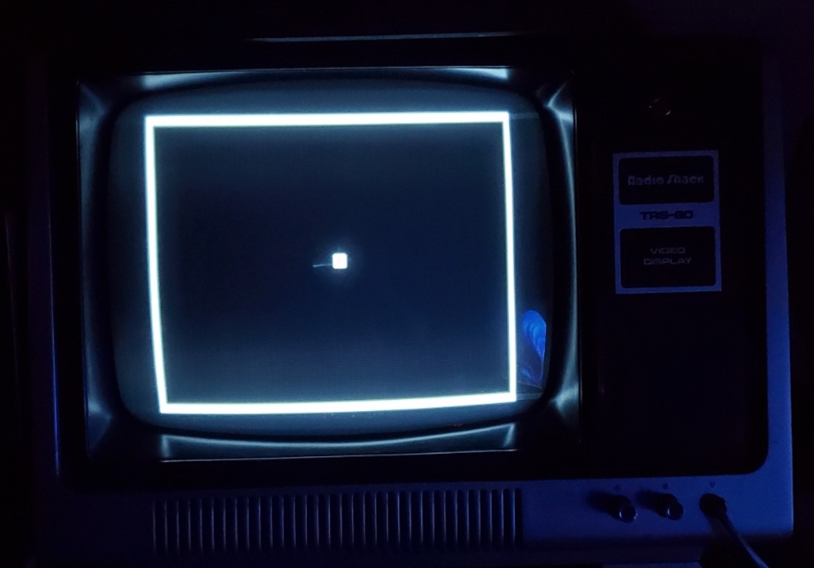
The TRS-80 test pattern running on the original TRS-80 video display monitor, all nice and centered.
Time to put a bow on it!
Expansion Interface: Things You Should Know

This guide was predominantly made to discuss the TRS-80 Model I computer itself as an extensive repair guide. However, I also embarked on an often similar troubleshooting effort for an expansion interface. Underneath the casing they share many similarities, including their own banks of RAM, controllers, matched capacitors and so forth. If you follow the basic principals above and review the schematics and guides specific to the EI, you should be fairly well-suited to repair any problems.
Rather than rehashing the usual, I want to just touch briefly on a few points:
- Read the Operator's Manual: Sometimes just reading the basic owner's manual for any of these devices can go a long way to understanding their expected behavior and operations, more-so than the technical references. Here's a great copy of the EI's manual that consumers were given, and it makes a light read while familiarizing you with all of its inputs and outputs. When I first ventured down this repair path and acquired an EI, I knew nothing about it so found this guide was enough to make me feel comfortable with how it should operate. Without reading it over, a person might think the TRS-80 itself has a defect if they turn it on while hooked to the EI and only see a garbage screen — but we learn that it does this always if there is no bootable drive media, and that holding down BREAK on boot (or BREAK + RESET) can put us back to BASIC.
- RAM Banks for 16K or 32K: The expansion interface supports an additional 32KB of RAM, bringing the total to 48K assuming you've maxed out the TRS-80 at 16K. If you are only installing 16K into the machine, you should install it to banks Z9 to Z16 instead of Z1-Z8 (which is the high memory allocation for the subsequent 16K). This felt backwards and led to a lot of time troubleshooting why I was not seeing any of the extra RAM when I had 16K in Z1-Z8. As with the TRS-80, you'll want to check all ICs to ensure nothing is getting scorched hot as well as test all RAM. To determine whether the EI is working correctly with expanded RAM, power up the TRS-80 while holding BREAK while connected to the powered on EI. Press ENTER on the "MEM SIZE?" prompt and then type: ?MEM and press ENTER. If you see around 15570 that means it is only seeing your internal 16K. Anything above that means it has added the RAM from the EI (e.g., 48338 if it is maxed out to 48K).
- Expansion Interface Connector Cable: The early models of the EI had major interference problems between the computer and the EI. So bad that there was an official "buffered cable" recommended to prevent random failures and glitches. The revised EI board resolved this solution and they recommended using a standard 40-pin cabling (6 inches or so in length) instead. There were also apparently issues with the edge connectors of these units corroding and causing malfunctions. In my repair efforts, standard 40-pin male straight headers are soldered onto both EI edge connectors (keyboard and EI). This allows for a standard IDE hard drive cable to connect. What caused me a major headache was that the cable I was using was three feet in length. Everything seemed to work okay at first glance. But when I'd boot into Level II BASIC and specify any explicit MEM SIZE especially over 30,000, it'd generally fail and corrupt the screen even though those bytes should be perfectly reservable with extra RAM. I spent way too long repairing all the sockets and solder points, testing and retesting RAM, swapping other components. Ultimately only to discover that the cable was simply too long for reliable connections. I now use the shorter end of that same cable, approximately one foot in length, and have no trouble at all. I will be replacing the cable with a more compact and stylish IDE cable in the future. A similarly difficult to detect problem occurred when I was trying to use a different interface cable that came with the set. Under very close examination I discovered several of the 40 wires had broken near the connector points so any task that required transmission on those pins would fail.
- Power Supply: The original setup for EIs required that you stick two full TRS-80 power supplies into the unit's case. One connected internally to the EI board, and the other ran out the back along with both electrical plugs. Make sure voltage is checked across the pins if using these old supplies to ensure nothing is impaired. I would recommend investing in a heavy duty modern power supply that can power both the TRS-80 and EI from a single outlet and is much more refined.
Before attempting any floppy drive hook-up or advanced configuration, you should focus on getting the TRS-80 perfected as well as the EI with maxed out RAM. Now would be a good time to re-test Level II ROM cassette loading and that all RAM is accounted for. With 48K total, you should be able to enter 60000 for "MEM SIZE?" and have BASIC load successfully, then see around 42801 available for BASIC when you type ?MEM. (The decimal value specified for "MEM SIZE?" actually refers to which memory location should be the final byte reserved for BASIC, with the rest being preserved for machine language routines or what not.
Floppy Drives
Originally, the TRS-80 Model I supported only single density (35 track) drives/disks though a floppy controller chip (FD1771) in the EI. These disks provided enough storage for up to around 85KB of content. Eventually double density controllers and adapters were manufactured to open the doors for double density 40-track disks with expanded storage capacity. Swapping floppy controllers was a simple effort, since they were already socketed. One popular adapter was Percom's Doubler II. This fit right into the original floppy controller socket, and within it you'd install the original FD1771 alongside a second controller it included. Over time, more disk drive manufacturers produced compatible double density hardware, and flavors of DOS started natively offering support.
The old 5.25" floppy drives ("mini disks" compared to the original 8" mammoths) are rather sophisticated internally and require their own schematics and service manuals to help troubleshoot. The good news is most drives from the era were relatively similar in operation and maintenance.
Before touching on some key takeaways to look out for when dealing with floppy drives, I again stress that you should do a full visual inspection of the drives inside and out before powering them up or attempting to read disks. One of my disk drives appeared cosmetically fine on the outside, but internally had very old paper-plastic electrolytics for the power supply run and two of them had exploded and were highly unstable.
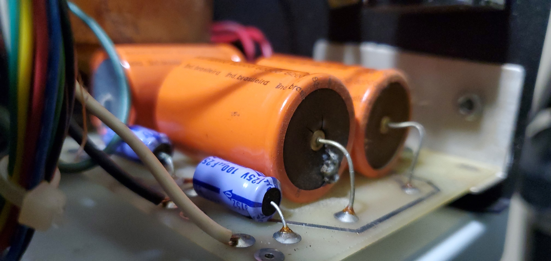
Always look over large electrolytic capacitors for any obvious signs of damage. Modern electrolytics are cheap and significantly less volatile than ones now 40+ years old.

The freshly replaced capacitors will help ensure years of maintenance-free operation.
A few important items to note:
- Head Cleaning and Rails: Over time the sensitive data-reading heads can collect even tiny specks of dirt that can hinder its ability to read floppy disks. Likewise, the rails that the head assembly traverse on can seize up as the original polish and lubricant dries up. You can find many tutorials online about floppy drive maintenance. Sometimes to get at the heads requires disassembly or removal of the top PCB. I usually gently brush against the heads with a non-lint foam brush containing either IA 91% or dedicated floppy contact cleaner such as from old stock Sony cleaning kits. In the glory days of floppies you could also find head-cleaning disks similar to VCR tape cleaners, but those have gotten fairly rare these days. If you have a long enough cleaning pad it is sometimes possible to clean the heads by going through the door opening without any more disassembly needed. I want to emphasize that great care should be taken especially lifting the upper head, if you lift slightly too much you can snap the arm off or destroy the alignment. For the rails, any sort of lubricant is sufficient and I've seen people use everything from dry lube to 3-in-1 oil; first clean them with IA 91% and then gently rub a tiny brushing of lubricant onto them. I'd avoid any lubricant that may bunch up as the assembly slides back and forth. Depending on the drive, sometimes you can manually slide the head back and forward to finish cleaning the rails, but do so with caution.
- Door Latch Failure: Certain popular models of Radio Shack floppy drives, notably the Tandon series, used short nylon pegs as part of the door lock mechanism. These break easily and then the door will not stay down. Once again I owe much gratitude to Larry Kraemer who supplied me with replacement rods, inset components and instructions to repair the broken drive I had in a much more permeant and robust solution. I'm not sure if any of these parts or instructions are distributed at large, but please reach out if interested in learning more,
 Terminating Resistors: In the TRS-80 days of computing, floppy drive cables could easily extend 10 feet with five branch-off points (one for the EI and four more to power up to four disk drives). For technical reasons it became necessary to terminate the last drive on the line using a specialized resistor pack that'd connect to the floppy's PCB. It is a pretty complex topic but a video from Adrian's Digital Basement helps explain it quite well. Radio Shack's original "Drive 0" mini disk drive (26-1160) came with the terminating resistor added as well as the floppy cable. They then sold an essentially identical drive as part number 26-1161 for use as drive 1-3. The only actual difference was that the subsequent drives did not include the cable or terminating resistor. For all practical purposes on two drive connections with relatively short cables, whether you have a terminating resistor in one or the other won't generally make a difference. All that matters is that you test both drives successfully and if something isn't working right, double-check for one terminating resistor.
- Drive Select: When dealing with multiple disk drives, determining the order of them used to be a somewhat convoluted process. Radio Shack's floppy cables for the expansion interface came with certain pins removed and users were advised to plug the drives in sequentially beginning from the expansion interface to drive 0-3. The pin removal was a clever way to automate the drive select allocations without having to fuss with on-board drivers or manually reconfigure drives when adding or removing any.
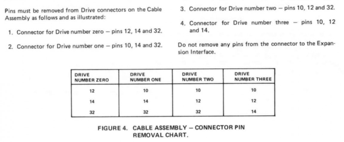
- Shunt Configurations: Another complicated feature related to drive selection of ancient floppy drives involved adjusting a shunt depending on whether you were using a single disk drive or multiple drives, what order you wanted them in, and other behavior. Most floppy manuals I've come across don't to a very good job explaining the various jumper settings and uses, but I found an excellent summary on pages 2-14 to 2-16 of the Siemens PU 670C manual. The pinout and items closely match what can be found on most TRS-80 floppy drives. The important part is that since the TRS-80 handles drive selection based on the selectively removed ribbon cable pins, DS0 through DS3 pins on all attached floppy drives should be enabled (shunted). The MX jumper should be cut/open, HS should be open and HM should be shunted.

All Hooked Up, But No Media!
Finally, everything is connected and running beautifully. And to think it only took me more than half a year a short stint of troubleshooting and repairs to reach this point! I'm finally ready to dive into the monochromatic goodness of TRS-80 and discover the thousands of programs for it. But I don't have any boot disks. And limited media even on cassette. Here are some options:
Cassette Transfers via PC/Laptop with Play CAS
 There are some excellent TRS-80 tools out there from passionate developers. One such tool is known as Play CAS. It allows you to open up any .CAS (virtual cassette) file for TRS-80 and easily play it through your soundcard, which can be connected to the cassette interface cable's black "Audio INPUT / headphone" line. Then on the TRS-80 you can load into Level II BASIC and either type CLOAD <ENTER> if the cassette is BASIC, or SYSTEM <ENTER> [?] <ENTER> (where [?] is the first letter of the program's title, viewable from Play CAS). As long as your audio output settings are correct on the PC and volume at a decent level, you can then press play on your computer and the audio will begin transmission. On the TRS-80 you should see two asterisks in the top-right corner, one will be flashing. Once it has completed, you can type RUN <ENTER> (if the cassette was BASIC) or / <ENTER> (if the cassette was machine language) to launch it. Note that it can take more than four minutes to transfer data via cassette at around 500 baud.
Play CAS also allows you to save out any .CAS file to a .WAV, which you can then play through any ordinary audio player or transfer to your phone to act as a mobile cassette deck. Be careful playing the files through any software that has equalizer effects and enhancements enabled. On my main computer with a Sound Blaster A7 card, I switch the output to "Headphones" and "Raw" to ensure no filter effects get applied before playing the audio in a media player or utility like Audacity.
Relatedly, the TRS80-Tool utility allows you to convert one format to another, so you can convert .CMD disk software to .CAS or .WAV to sent to the Model I without requiring a floppy at all (e.g., "trs80-tool convert game.cmd game.cas" then play that through Play CAS).

A 32K cassette-based game successfully transferred from a computer to a physical TRS-80 via audio out and Play CAS software.
Creating Bootable DOS Disks with a Cassette Bootstrapper
Now for the real exciting stuff. How do we go about making fresh 5.25" floppy disks usable on our TRS-80 disk drives? Without them our entire disk drive setup and EI is somewhat irrelevant.
I have a Model III but it is diskless with a M3SE interface, so I can't exactly make floppies from that. Plus my initial aim is to create single sided 35-sector versions of the popular DOS variants, so there might be conflict attempting that from a Model III anyway (I never tried).
One approach requires a chain of tools and blind luck that you have a supported 360K 5.25" ready computer for disk transfers. This process was illustrated well back in 2018 from Adrian's Digital Basement. The general approach is to extract the desired files from virtual DSK files or use them as-is. Then using ImageDisk / DMK2IMD you can convert the file to a compatible format to then copy to a floppy after setting some very specific properties. This is not a half bad approach and, once you do it a few times, enables you to create fresh floppies of any data you want from a PC environment. All contingent on you having other legacy machines capable of such, that is.
But there's a much more entertaining and rewarding way to go about doing it, and in my experience was actually less error-prone and tedious than the roundabout PC method.
Introducing... TRS-80 DOS Cassette Bootstrapper
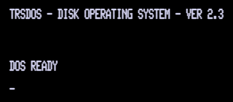 Developer Jürgen Büssert realized that by creating a simple cassette-based bootloader, he could then feed it raw byte data track-by-track encoded as audio. He then converted all major flavors of TRS DOS into an audio byte format for use with the bootstrapper.
It takes a very long time.
This method requires you have an expansion interface and a total of at least 32K of RAM, and that your floppy drives, floppy disks and cassette interfaces are all operational. Then you can grab the FLAC files from his site or even load them on your phone connected to the cassette interface as previously explained. You then do as follows:
- Insert a new/wiped floppy drive into your TRS-80 disk drive.
- Power on the EI and then the computer while holding in BREAK to enter Level II BASIC.
- Enter 40000 for MEM SIZE? to ensure enough space is reserved for the actual cassette track data.
- Type SYSTEM <ENTER> B <ENTER>
- Play the bootstrapper file named something like bootstrap.v7.5.500.flac
- After 3+ minutes when it is done, press / <ENTER>
- A prompt will then appear asking what disk drive you wish to use (0 for primary) and then to confirm (1).
- Now, play whatever version of DOS you wish to load onto the disk, such as Model I - NEWDOS80 2.0.500.flac
- After the first block of data the disk should begin formatting. Assuming it is successful, the audio will continue playing and load track-by-track to then write and verify to the disk.
Since these operating systems have 35 to 40 tracks, the average playtime is 30-40 minutes. If any track fails during the process or there are other disk or drive issues, it will halt. If all is successful, it will say the writing is complete and you can then reboot your machine normally and DOS should take over! If not, you'll have to run the entire process again including starting with the bootstrap audio. I recommend trying a different disk if one fails.
This approach is clever and the same theory could be applied with the existing bootstrapper to create additional cassette-based disks of any sort, to enable users to create new disks directly from a cassette interface alone.
As each one finished, I used a vintage but excellent label maker and Windows 95 to print up some custom labels.
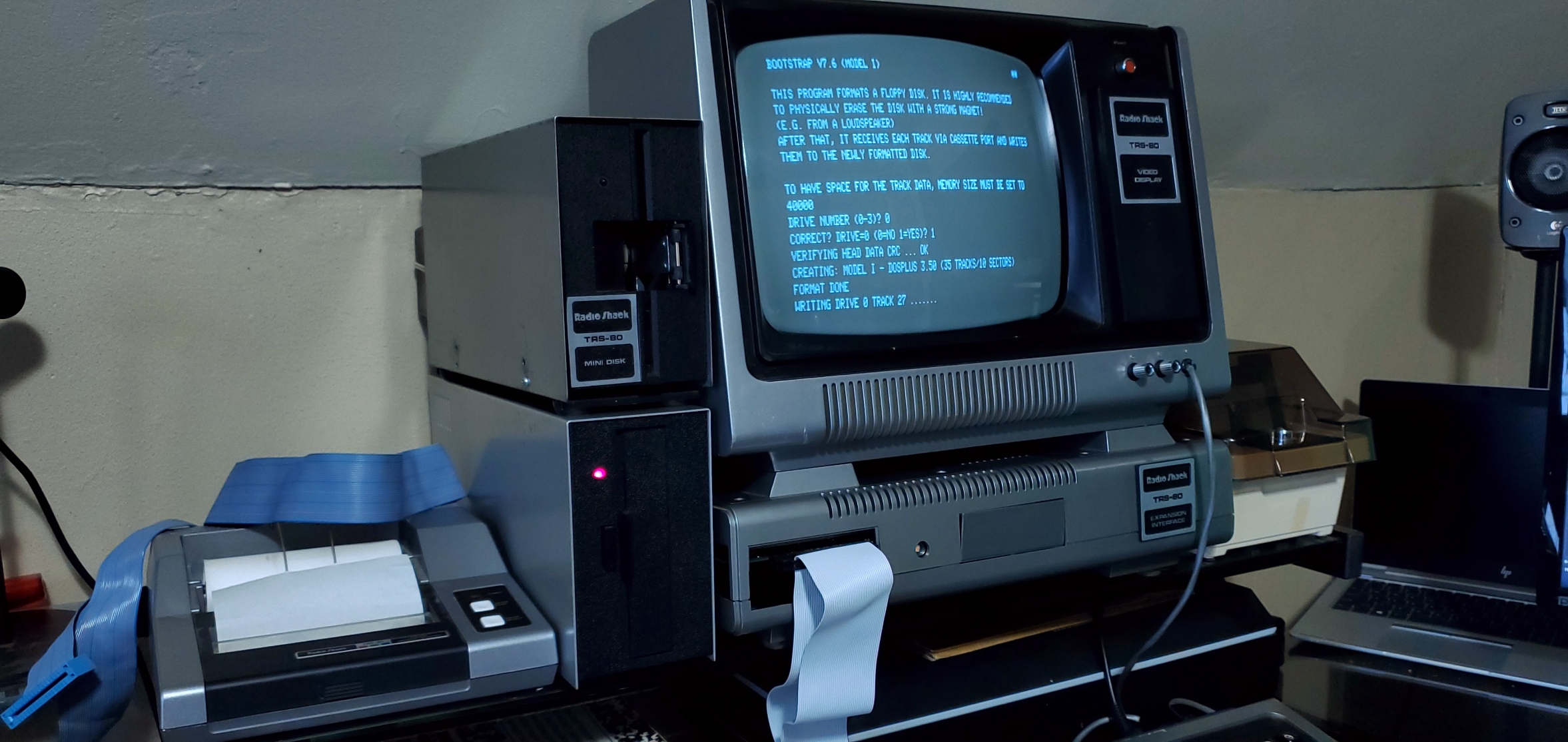
Successfully transferring an entire disk operating system for TRS-80 from a cassette interface, one track at a time.
Using an old Windows 3.1 / 95 floppy-based label editor to create labels for the new DOS disks.
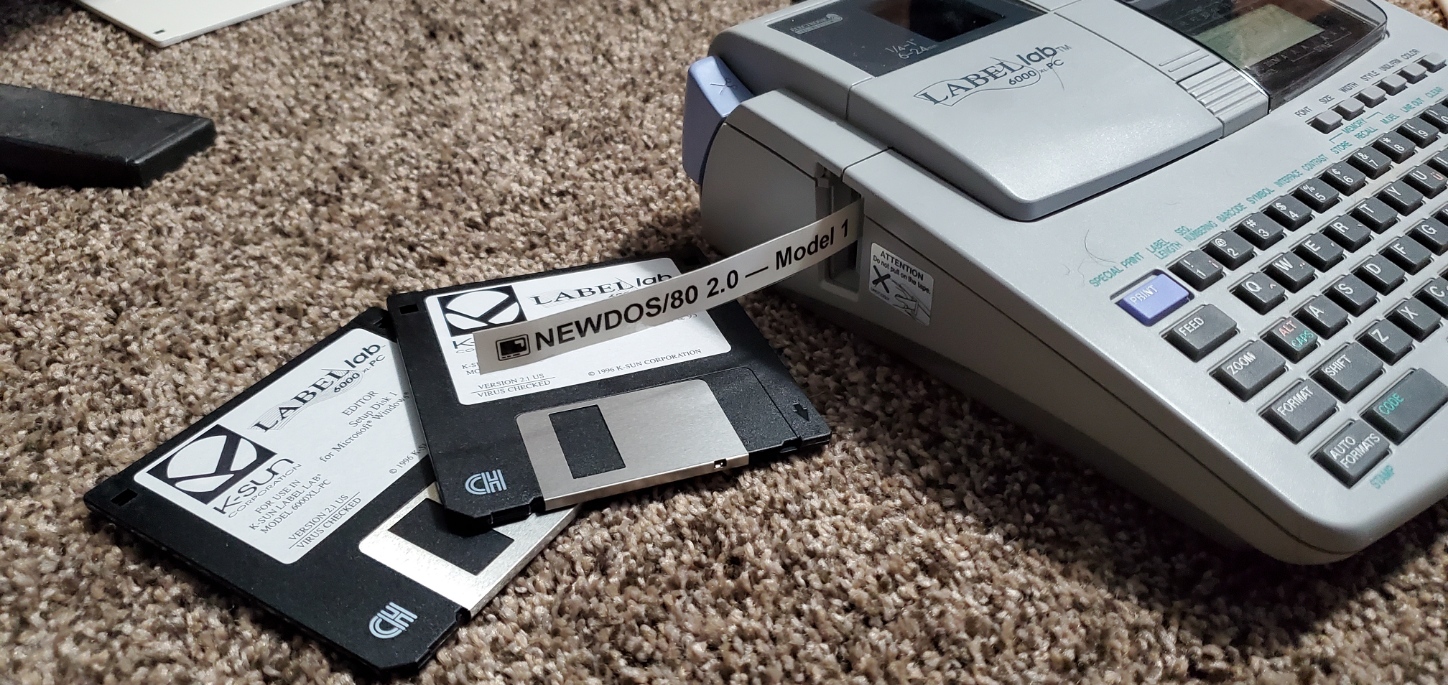
Labels printed from a Windows 95 Packard Bell via serial to a Label Lab 6000 label maker, which is still a very useful machine!

Archiving Cassettes and Floppy Disks
A massive amount of TRS-80 Model I applications on cassette and floppy are already archived in some form or another online. Willus.com has the "Big List of TRS-80 Software" that itself encompasses 15,871 entries at the time of this writing. Even so, you may have homebrew cassettes, rare newsletter compilations, diskettes containing data, audio commentary or other files that have never been digitized. I've acquired piles of unlabeled cassettes and disks as part of random computer bundles in the past, contents unknown.
Magnetic storage is prone to deterioration so the sooner that archiving is attempted, the better chances you have of success. You may also encounter other problems along the way, such as severed tape, but with care much of this can be remedied at least to the point of attempting to read the contents. It was also common to record the same data several times on both sides of a tape for backup purposes, so if one track of cassette data fails, there may be another copy elsewhere to try.
Cassette Backups
This is an easy process but one that requires some amount of trial and error. You'll want to get a reliable cassette player that supports headphone/speaker out. I use a trustworthy Radio Shack CTR-69 Voice Actuated Cassette Recorder for my successful backups. Before hooking any external inputs up, I recommend playing a standard music cassette to verify the sound is good and playback works as expected. You may also want to clean the cassette heads, a lazy way of doing so is to just play a new blank cassette tape straight through (this applies to VCRs, as well). With this system and the cassettes I've been transferring, I have found the following settings work well:
- VOX - Out
- ALC - Out
- Tone - 10
- Volume - 5 (can vary depending on the cassette's recorded volume)
When you know the cassette player is working, you can run a cable from its HEADPHONE/SPEAKER out port to your computer's LINE-IN port. Depending on your setup, this port is often software-toggleable between MICROPHONE and LINE-IN. With my Creative Sound Blaster AE-7, an external docking peripheral is included that allows easy connection to headphones and microphones using 1/8" or 1/4" connectors.

Make sure your input device for digitizing cassettes is set to Line-In.
If your sound card has a multipurpose port for input, you will want to ensure LINE-IN is activated through software to get much cleaner captures than anything possible with MIC. With Sound Blasters, this is done via Sound Blaster Command → Mixer → Recording → (Gear Icon) → Line In. You will find similar software options with other hardware configurations, including most onboard configs like Realtek HD audio. I then prefer to go into Windows' own Control Panel → Sound → Recording and set Line-In as the default, then open its properties and set the volume level to 70 (but again this may vary by player and cassette audio volume).

Successful digitization of a SoftSide cassette tape, from physical cassette to computer to online cassette parser and emulator.
Then, using your audio recording software of choice (e.g., Audacity, Audition) create a new 22,050 Hz, 16-Bit Mono track. Make sure the input for the software is set to Line In and then you can play the cassette and record on the computer to capture the waveform. I'd recommend letting the full side of tape play before stopping the recording, and then save it as an uncompressed WAV. While playing the audio, monitor the decibel level and adjust the volume accordingly. Usually with tape transfers the louder the better, but I have found keeping the complete waveform from -6 to -1 tends to produce an accurate record. Even if the audio clips above 0, it should be fine in many instances.
Now for the magic. The open source suite of TRS-80 tools includes an amazing web application for TRS-80 cassette analysis and restoration. By visiting https://www.my-trs-80.com/cassette/ you can load in your complete WAV file, and it will clean and reconstruct it into as perfect a transfer as possible. It also allows you to preview the binary data, BASIC coding, or even emulate it. It also will break up each track into its own section, and other handy features. Even if the transfer was partially corrupt, you can usually decipher metadata from the binary data including authorship or title, and then use that to research other copies online. The best part is you can then save a copy of the BAS, CAS and RECONSTRUCTED WAV to have a pristine backup of the data for future use on real or emulated devices.
Disk Backups
There are a lot of online resources explaining how to backup disks from a variety of systems and also the precautions of attempting so. You typically need some specialized hardware or software to make byte-for-byte backups on modern systems. Some old software may also have copyright protection tricks that will make ordinary reading or backing up more difficult.
Ira Goldklang offers a backup service free-of-charge, for converting Model I, III or 4 disks into DMK virtual disks. More details here: http://www.trs-80.com/wordpress/faq-converting-your-disks/
There are also some dedicated controllers, such as greaseweazle, that can enable you to read a huge array of floppy disks on a modern machine. I have an FC5025 USB 5.25" Floppy Controller but have not explored its compatibility with my TRS-80 Model I/III disks (the site notes compatibility with Tandy Color Computers but no mention of Model Is).
Finishing Touches and Conclusion
The TRS-80 had no internal sound chip or speakers. The TRS-80 monitor was likewise stripped of any audio mechanism. Yet, the systems are very capable of playing digitized sound by hijacking the cassette interface. This became a popular feature in some of the most iconic games, including those by Big Five Software. All you have to do is hook any sort of speaker amplifier up to the microphone out port and play a compatible game or software program like the Berzerk-inspired Robot Attack. Naturally if you hook up a speaker, you'll either need a y-adapter splitter or audio switch to toggle between speaker and cassette microphone in the event that you need to save any data via cassette.
At one point I also picked up an old Radio Shack CGP-115 four pen color plotter. It looks nice alongside the setup but I have to source some of the small specialized ink pens for it. Given their obscurity, this seems more like a 3D printing project to create the casings and then some makeshift ink tubes and pen tips.
I have a Doubler II in the expansion interface, and one double density disk drive alongside the original single density Radio Shack (Tandon TM100) drive. This allows me to get the best of both worlds while still having everything remain era authentic. The support for double density 40-track disks and similar should also make it easier to copy contents from an ordinary computer over to the system without having go through the maze of legacy software products and converters.
What I haven't decided is whether or not I will be getting a MISE for this set or leaving it in a vanilla state. Bartlett Labs makes incredible components for the Model I and Model III. On my diskless Model III that I rescued as a giveaway and restored, I do have a M3SE and love it very much. It enables WiFi, VGA output, joystick controllers and SD-based hard drive emulation. There is a lot of temptation and convenience to that approach for file transfers, so eventually I'll probably buckle down and get one. Or, at a minimum, a FreHD by Ian Mavric.
For now though, I just want to enjoy the simpler times of 1977 and immerse myself in all that the TRS-80 had to offer. To kick that off I've ordered two brand new games that have recently been developed for it:
- RoundUp! by Peter Cetinski (PSKI Software Development)
- Gem Hunter by Nickolas Marentes
A final word of thanks to all those who helped me on this journey toward restoration and TRS-80 appreciation, including: Larry Kraemer for his decades of experience, patience and repair materials. Ian Mavric for offering many hard to come by TRS-80 components that I needed including a character generator, power switches and more, Jay Neworth for the assembled modern heavy power supply, Ian Goldklang for the monumental TRS-80 informational site, George Phillips for creating an incredible emulator that I used often while troubleshooting my real device, Bartlett Labs for the MISE/M3SE, and all who are part of the TRS-80 communities.
I recommend you run all of your TRS-80 peripherals through a dedicated surge protector, so that you can turn the entire strip off after powering down to prevent the power adapters from continuing to run, etc.
External Resources
I've embedded some excellent third party hyperlinks throughout this article, but a few notable and additional mentions are below. You'll find much more through your favorite search engine but these pages are enough to keep one busy for a lifetime.
- Ian Mavric's FreHD Project
- Bartlett Labs TRS-80 MISE/M3SE Devices
- Ira Goldklang's TRS-80 Revived Site
- Play CAS (Play CAS files from PC through the TRS-80 cassette interface)
- TRS80-Tool (Convert many formats to many others and more, companion website)
- The Big List of TRS Software (Make heavy use of the search filter because there is so much content)
- CPM Archives TRS Library
- Tim Mann's TRS-80 Pages
- TRS80GP (Incredibly faithful emulator, useful for converting BASIC to CAS or testing any number of configurations)
- TRS-80 Books, Magazines and Manuals
- Modern TRS-80 Games
- Matthew Reed's TRS-80 Site
- TRS-80 Model I Internals
- RMC - The Cave: Trash to Treasure TRS-80 Restoration
Discussion Groups and Communication Outlets
Pingback: TRS-80 Model 1: Creating New Floppy Disks in 2022 (Two Methods) | Matt's Repository
So... I've experienced the same dreaded broken pegs issue in one of my Mod3 drives. Can you connect me with Larry Kraemer so that I can repair what was an otherwise flawlessly operating drive? THANKS!
What a great read, thanks for sharing this!
Note, I see from the pictures above you are using an older pcb for the new power supply. If you are using 120v, those transformers, as speced, are under powered when using both the m1 and ei. I and others have experienced voltage sags and flaky behavior. You might want to look into version 1.2 from Ian with new transformers.
Pingback: Retro Fix: Montgomery Ward CyberVision 2001 (Work In Progress) | Matt's Repository
Pingback: TRS-80 Model I restoration - Vlado Vince
Pingback: Road meet rubber – RACS III
Pingback: Road meet rubber – RACS III
Pingback: Tandy TRS-80 Model I – Mundocaos